
22w stereo amplifier
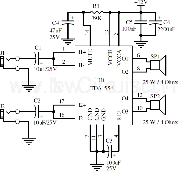
The TDA1554 is a dual power amplifier designed for car audio applications but is also suitable for various audio amplification tasks in home or portable audio systems. The amplifier's configuration allows for bridge operation, which enhances the output power while maintaining sound quality.
The circuit typically includes input capacitors to block any DC offset from the audio source, ensuring that only AC audio signals are amplified. The output stage connects to a speaker load, which must be carefully selected to match the amplifier's output capabilities, usually around 4 to 8 ohms.
To ensure the amplifier operates efficiently, it is essential to provide a stable 12V power supply that can deliver the required 5A current without significant voltage drop. The heatsink selected must be capable of dissipating the 28 watts of heat generated during operation, and thermal management should be considered to prevent thermal runaway conditions.
In addition to R1, other passive components such as capacitors and inductors may be included in the circuit to filter noise and stabilize the power supply. Feedback loops may also be implemented for improved linearity and reduced distortion, enhancing the overall audio quality of the amplifier.
The layout of the circuit board should minimize the length of the traces connecting the power supply and output stages to reduce inductive and resistive losses. Proper grounding techniques must be employed to avoid ground loops, which can introduce hum and noise into the audio signal.
Overall, this amplifier circuit is an effective solution for users seeking a reliable and straightforward method to amplify stereo audio signals, suitable for both novice and experienced electronics enthusiasts.Here is the 22 watt stereo audio power amplifier circuit diagram based on TDA1554 and integrated circuit from NXP semiconductors (formerly PHILIPS semiconductors). It is very simple and useful circuit for amplify the stereo signals. The circuit dissipates roughly 28 watts of heat, so a good heatsink is necessary. The chip should run cool enough to touch with the proper heatsink installed. the circuit operates at 12 Volts at about 5 Amps at full volume. Lower volumes use less current, and therefore produce less heat. R1 is also a 5% resistor. 🔗 External reference
Related Circuits
The Zen single-ended MOSFET amplifier was published by Nelson Pass in The Audio Amateur. In a subsequent issue of this magazine, Nelson slightly improved the original design. The "Revisited" version includes the following circuit modifications: 1. More extensive power supply...
Simple circuitry suitable for moving-magnet cartridges. Passive high-frequency equalization. This simple but efficient circuit devised for cheap moving-magnet cartridges can be used in connection with the audio power amplifiers shown in these webpages, featuring low noise, good RIAA frequency...
A common telecoil follows the MM formula (magnetic-acting) and has an impedance of approximately 600 ohms to effectively receive signals. It is necessary to reduce the impedance in the high-frequency segment, which is achieved by placing a 150pF capacitor...
This circuit turns off an amplifier or any other device when a low-level audio signal fed to its input is absent for 15 minutes at least. Pushing P1, the device is switched on, feeding any appliance connected to SK1....
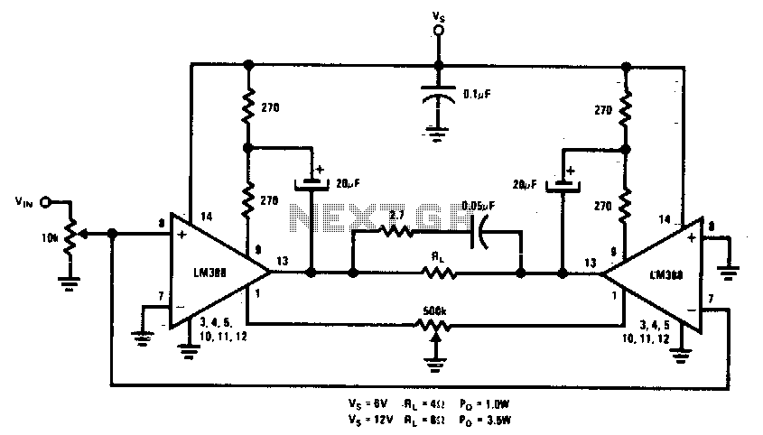
This circuit is designed for low voltage applications that demand high power outputs. Typical output power levels are low into 4 ohms from 6 V and 3 V into 8 ohms from 12 V. Coupling capacitors are not required...
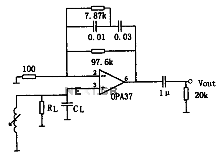
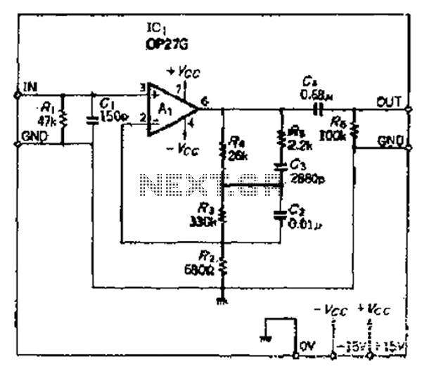
The OPA37 serves as a low-noise preamplifier. The input signal is connected to the inverting input of the OPA37 (pin 3), while the circuit components RL and CL represent the load impedance for electromagnetic pickups. The resistance and capacitance...