
250 kV High Voltage DC Power Supply with Neat Trick for Switching Polarity
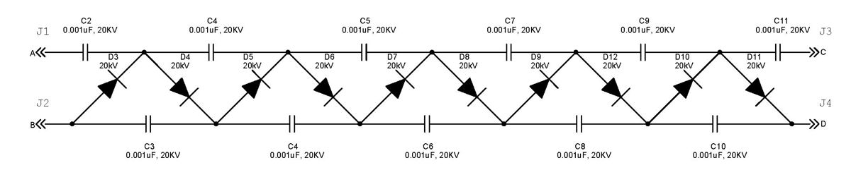
The Cockcroft-Walton multiplier circuit is a critical component in high-voltage applications, particularly in experimental physics settings. The design intricacies allow for flexibility in output polarity, making it suitable for various experimental setups. The use of diodes in conjunction with capacitors enables efficient voltage multiplication, where each stage of the circuit incrementally boosts the voltage level.
The selection of components, such as the flyback transformer, is essential for achieving the desired output. The push-pull oscillator configuration is advantageous for maximizing energy transfer and ensuring stable operation of the transformer. The choice of wire gauge for the primary windings is also significant; #18 wire is robust enough to handle the high currents while minimizing resistive losses.
Sealing the connectors with silicone RTV is a necessary precaution to prevent moisture ingress, which could lead to electrical failures. The immersion of the circuit in mineral oil serves a dual purpose: it acts as an insulator to prevent arcing and also dissipates heat generated during operation, enhancing the reliability of the system.
It is crucial to note that working with high voltages requires stringent safety measures. The design should include appropriate insulation, grounding, and protective enclosures to prevent accidental contact with live components. The operational limits of the system should be well understood, as exceeding voltage ratings can lead to dangerous conditions. Proper testing and validation of the circuit should be conducted in controlled environments to ensure safe and effective operation.The Cockroft-Walton multiplier uses a cascaded series of diodes and capacitors to generate a high voltageDC potential from anAC input through acircuit topology thatuses diodes to charge capacitors in parallel and discharge them in series. The output polarity of the Cockroft-Walton multiplier depends on the way in which its diodes are oriented, so
the output polarity(referenced to ground)of a high-voltage DC power supply is usually set during the design. However, since some of our physicsexperiments requireone or the other polarity, we build our Cockroft-Walton multipliers with an extra capacitor so that we can make our HV power supplies output either positive or negative high voltage referenced to ground.
The schematic for our reversible Cockroft-Walton is shown in the following picture (click to enlarge): If the high-voltage AC output of the flyback is connected to point A of the voltage multiplier, and point B is connected to ground, then the output at point D will be positive. If however point C receives the high-voltage AC, and point D is connected to ground, then point B will be negative.
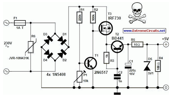
Banana connectors are theninstalled onthe plastic container and wired directly to points A, B, C, and D. The connectors must be sealed very well using silicone RTV: The plastic container should then be filled with pure mineral oil (may be purchased at a pharmacy) to completely submerge the multiplier circuit assembly, which prevents high voltage breakdown between components: In this AC power supply, a push-pull oscillator drives a TV flyback transformer from an old color TV (a flyback without embedded tripler).
The well-known hack is that the original primary of the flyback is not used. Instead, new primaries are made by winding two sets of four turns each of insulated #18 wire around the exposed core of the flyback transformer. Feedback for the oscillator is obtained through an additional coil of 4 turns of #24 wire wound around the core: As shown in the picture above, we built the low-voltage DC power supply right into the chassis.
We vary the voltage using an external variac (not shown in the pictures). In our power supply, 12 V applied at the input of the flyback driver produces around 250 kV DC at the output of the multiplier. We have measured up to 300 kV DC at higher input voltages, but the corona and breakdown get very scary, so we haven`t tried pushing the limit.
🔗 External reference
Related Circuits
An increasing number of appliances draw a very small current from the power supply. If designing a mains-powered device, it is generally advisable to consider the current requirements. The trend of modern appliances utilizing minimal power consumption necessitates careful consideration...

This is a 50-watt audio power amplifier circuit based on the single IC STK4036II. A heatsink is required to prevent overheating of the IC. The amplifier circuit provides good sound quality at an affordable price and is easy to...
In the monostable mode, the resistor can be replaced by a constant current source to provide a linear ramp voltage. The capacitor still charges from 0 to 2/3 Vcc. In a monostable multivibrator configuration, the circuit typically consists of a...
The aim of this project was to develop a linear analogue amplifier designed for laboratory use. This amplifier has to realise a voltage amplification of 10x and is intended to amplify function generator signals for tests. Power supply requirements:...

The circuit illustrated in the figure features an automatic voltage regulator (T) that utilizes a servo motor to ensure a constant output voltage. The transistors used are VT1 and VT2 (3DK9C, with a range of 65 to 85) and...
The success or failure of lighting upgrades depends on the quality of components and workmanship. Proper wire routing is essential to prevent insulation chafing. The quality of soldering connections is crucial, as poor solder joints can corrode and fail....