
Linear voltage ramp generator
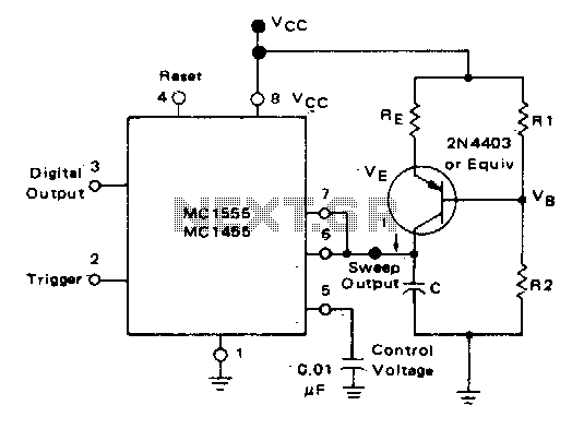
In a monostable multivibrator configuration, the circuit typically consists of a timing resistor, a timing capacitor, and a trigger input. When a trigger pulse is applied, the output transitions from a low state to a high state for a predetermined duration, determined by the RC time constant.
In this specific configuration, the resistor can be substituted with a constant current source, which allows the capacitor to charge at a linear rate rather than an exponential rate. This modification enables a more predictable and controlled ramp voltage across the capacitor. The linear ramp voltage is particularly useful in applications requiring precise timing or signal shaping.
As the capacitor charges, it progresses from an initial voltage of 0 volts to a maximum of 2/3 Vcc, where Vcc represents the supply voltage. The time taken for the capacitor to reach this threshold can be calculated using the relationship between the constant current, capacitance, and voltage change. The formula governing the charging behavior in this scenario is derived from the basic capacitor charging equation, modified to account for the constant current source.
The output of the monostable multivibrator will return to a low state once the capacitor voltage reaches the threshold of 2/3 Vcc, effectively terminating the output pulse. This characteristic makes the circuit suitable for various applications, including pulse width modulation, timers, and signal conditioning, where a precise output pulse width is essential.
Overall, the integration of a constant current source in place of a resistor in a monostable configuration enhances the linearity of the voltage ramp, providing improved performance in timing applications.In the monostable mode, the resistor can be replaced by aconstant current source to provide a linear ramp voltage The capacitor still charges from 0 to 2/3 Vcc. 🔗 External reference
Related Circuits
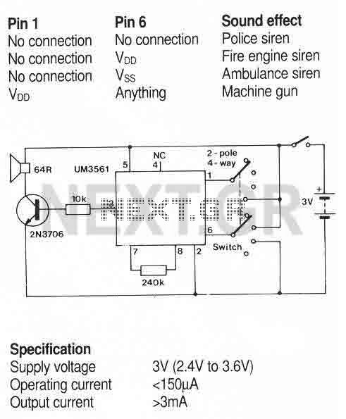
A simple sound generator IC that can produce four sound effects. Designed for use in toys, the effects are selected by varying the connections to pins 1 and 6 as follows. More: A usual toy sounder IC circuit. The sound...
This circuit enables a smaller control voltage to inversely and linearly control a larger output voltage (Vo). Additionally, the supply voltage (Vsp) for the operational amplifiers can be lower than the output voltage, allowing the circuit to theoretically control...
This circuit incorporates a datasheet-compliant trigger signal, reversed polarity protection, an optional test button, and the capability for battery operation. It utilizes either the U1 L601E3 or MAC97A8 triac, rated for 400 V and 1 A. When U1 is...
This is a basic flash memory programming voltage supply circuit. This circuit utilizes the LT1072 switching regulator to generate high voltage by driving the inductor L1 and resistor R2. The basic flash memory programming voltage supply circuit is designed to...
That RF Amplifier is for boosting small fm transmitters and bugs. It uses two Philips 2N4427 and its power is about 1 Watt. At the output, you can drive any linear with BGY133 or BLY87 and so on. Its...
This circuit addresses the challenge of transmitting data over a cable that lacks available conductors. The data is modulated using On-Off Keying (OOK) and superimposed on a high-frequency carrier, allowing it to be transmitted over a low-voltage power supply...