
250 to 5000 watts PWM DC/AC 220V Power Inverter
R2 is used to set the frequency to either 50 or 60 Hz (with a range between 40 Hz and 75 Hz). Users without a frequency meter are advised to set this variable resistor to the midpoint, which should yield a frequency in the 50-60 Hz range. To achieve a fixed 50 Hz output, both the 100K and variable 100K resistors should be removed from pin 6, and a 260K fixed resistor should be used in their place, while leaving the 0.1uF capacitor (the 104 cap) unchanged. This modification should provide a near 50 Hz output; however, due to tolerance errors in the resistor and capacitor, a variable resistor is recommended for precise calibration.
It is advised to use tantalum or polyester film capacitors for the 104 caps, as ceramic disc capacitors can change value when heated, affecting the inverter's frequency. Pin 10 of the SG3524 can be utilized for automatic shutdown of the inverter. When a positive voltage is applied to pin 10 instead of negative, the SG3524 will cease oscillation, which is beneficial for implementing features such as overload cutoff, low battery cutoff, or overheating cutoff.
Wiring connections on the power stage side must be sufficiently thick to accommodate the significant current draw from the batteries, as indicated by dark black markings on the schematic. The design does not include a battery charger, allowing users to build a custom inverter tailored to their specific power needs. If ordering a custom transformer, it is possible to request an additional output wire on the primary side to provide 14V (between point 0 and this new wire) for charging a 12V battery; however, this requires a separate circuit for automatic cutoff and is not advisable as it may reduce the transformer's lifespan due to overheating of the copper wire enamel.
A cooling fan is necessary to dissipate heat from the heatsinks and transformer. A 220V fan connected to the T2 transformer output can serve as an indicator of 220V presence when the circuit is powered. A computer power supply fan may be repurposed for this task.
It is crucial to note that if the design utilizes more than 24VDC as a power source, the driver circuit should not be supplied with more than 24V. For instance, with four 12V batteries totaling 48V, the driver circuit's positive supply should connect to the second battery's positive terminal using a thin 1 mm wire, ensuring the driver circuit receives +24V while the power transformer operates at +48V.
Caution is advised when constructing this circuit due to the involvement of high voltage components.
The inverter circuit design incorporates various features and considerations for scalability, safety, and efficiency. The modular approach allows for power adjustments by adding transistors and modifying the transformer, while the careful selection of components ensures stable operation and frequency regulation. Additionally, the inclusion of safety features and cooling mechanisms enhances the reliability of the inverter system, making it suitable for various applications requiring custom power solutions.The schematic circuit design is for a 250 watt output, while the pics are of my 1500 watts inverter that i built, to increase the power of the circuit you have to add more of the Q7 and Q8 transistors in parallel, each pair you add will increase your power by 250 watts, ex: to get 750 watts of power from the inverter you need to add in parallel 2 of Q7 and 2 of Q8 to the original design. 2> If you increase the power transistors you have toenlarge the T2 transformer to match the new needs, the circuit`s transformer is rated 25 amps to handle 250 watts of 220v, for every 1 additional amp you need on the 220v side you have to increase 10 amps on the 12v side, of course there are limits to the thickness of the winding so if you need more than 750 watts i recommend that you use a 24VDC supply instead of 12 volts: 4> R2 is to set the frequency to 50 or 60 Hz (R2 range is between 40Hz to 75Hz), so guys that do not have a frequency meter are advised to blindly put this variable resistor mid-way which should drop you in the range of 50~60 Hz. in our case to get a 50Hz output we remove both the 100K and the variable 100K both from pin 6 and we put instead a 260K fixed resistor and we leave the 0.
1uF (the 104 cap) as it is, this change should give out a fixed 50Hz as per the formula : But in reality it will not exactly give 50Hz because the 260K resistor has a specificerror value marginso does the capacitor, that`s why i recommend a variable resistor so that accurate calibration can be achieved. 5> Use either tantalum or polyester film "as in pic" for the 104 caps, ceramic disc caps change value once hot and this in turn changes the frequency of the inverter so they are not recommended.
6> Pin 10 of the SG3524 can be used to auto shut down the inverter, once apositive voltage isgiven instead ofnegative to pin10, the SG3524 will stop oscillating. This is useful for persons wanting to add some cosmetic makeup to their inverters like overload cutoff, low battery cutoff or overheating cutoff.
7> Wiring connections on the power stage side should be thick enough to handle the huge amps drain from the batteries. I marked them with dark black on the schema also I includeda pic so you see how thick those wires must be.
8> The design does not include a battery charger since each person will be building a custom version of the inverter with specific power needs. If you are ordering a custom made transformer you can ask them totake out foryou an additional output wire on the primary side to give 14v (between point 0 and this new wire) and use it to chargea 12vbattery, of course this needs a seperate circuit to control charging auto cut-off.
But anyway this is not advisable because it will shorten the life of the transformer itself since using it as a charger will toast the enamel coating layer of the copper wires over time. Anyway. YES can be done to reduce cost. 9> A cooling fan will be needed to reduce heat off the heat sinks and transformer, i recommend getting a 220v fan and connecting it to the output T2 transformer, when you power up the circuit the fan will start this will always give you a simple way to know that 220v is present and everything is OK.
You can use a computer`s old power supply fan if you like. 12> Important: If you`re building a big design that uses more than 24VDC as power source, make sure not to supply the driver circuit with more than 24v maximum. (EX: If you have 4 batteries 4x12 = 48v, connect the v+ supply of the driver circuit to the second battery`s (+) terminal with a thin 1 mm wire which is more than enough.
this supplies the driver circuit with +24v while supplies the power transformer with +48v)"see the batteries pic example" 14> Be cautious when building this circuit it involves high voltage whic 🔗 External reference
Related Circuits
This document discusses the advantages and disadvantages of various power supply technologies, along with the design considerations necessary for selecting and evaluating a mains transformer. It covers the pros and cons of external supplies, inrush current control, RF emissions...
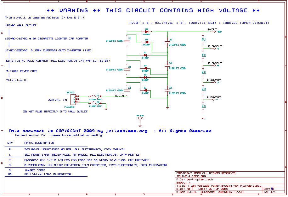
This high voltage, low current power supply has been designed for various experiments in systems and synthetic biology. The schematic and board layout are provided below. The circuit can output up to +1,866 VDC at under 1 mA and...
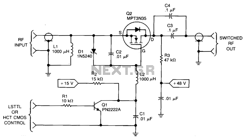
This RF power switch operates at 1.7 MHz with a 50-V source and load. Its on-loss is 0.2 dB, and its off-isolation is 30 dB. It provides 40-W PEP, 45 V_RMS, and 0.9 A_PEAK. The control input can come...
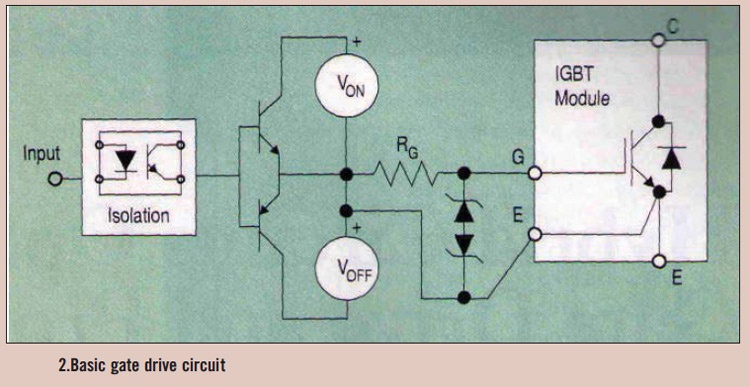
High power IGBT modules utilize hybrid integrated circuit (IC) gate drives that incorporate protection circuits, which implement desaturation detection or real-time control. High power Insulated Gate Bipolar Transistor (IGBT) modules are essential components in various high-efficiency power conversion applications, such...
The two circuits below illustrate opening a relay contact a short time after the ignition or light switch is turned off. The capacitor is charged and the relay is closed when the voltage at the diode anode rises to...
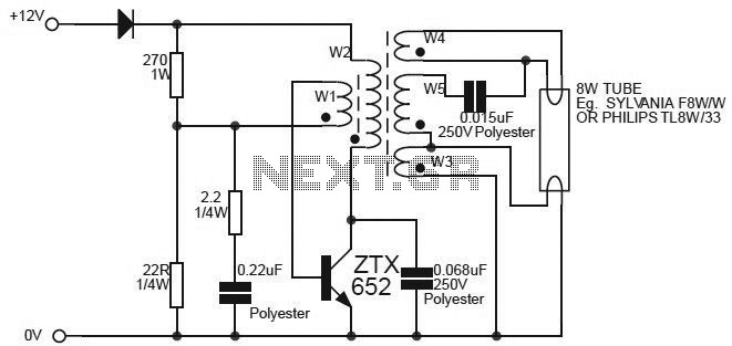
This circuit is essentially an 8W inverter circuit designed to drive an 8W fluorescent lamp from a 12V power supply. It utilizes an inexpensive inverter based on a ZTX652 transistor. The inverter will operate efficiently to convert the DC...
Warning: include(partials/cookie-banner.php): Failed to open stream: Permission denied in /var/www/html/nextgr/view-circuit.php on line 713
Warning: include(): Failed opening 'partials/cookie-banner.php' for inclusion (include_path='.:/usr/share/php') in /var/www/html/nextgr/view-circuit.php on line 713