
25W Mosfet audio amplifier
The described circuit functions as an audio amplifier capable of interfacing directly with various audio sources such as CD players, tuners, and tape recorders. The design incorporates a dual gang 10K logarithmic potentiometer, which allows for stereo volume control, and a switch to select between different audio sources. This flexibility is essential for users who require a versatile audio setup.
The amplifier is specified to deliver an output power exceeding 25 Watts RMS into an 8 Ohm load at a frequency of 1 kHz. This power output is significant for driving typical speakers in home audio applications. The input sensitivity of the amplifier is noted to be 200 mV for achieving the 25 Watt output, indicating that it can effectively amplify low-level audio signals without requiring excessive input voltage.
The frequency response of the amplifier is specified as 30 Hz to 20 kHz with a tolerance of -1 dB. This range covers the full audible spectrum, making the amplifier suitable for a wide variety of audio content, from deep bass to high treble frequencies.
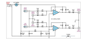
Thermal management is addressed in the design, with specific components requiring heatsinks to dissipate heat generated during operation. Transistors Q6 and Q7 are to be equipped with small U-shaped heatsinks, while Q8 and Q9 require larger heatsinks for effective thermal regulation. Proper thermal management is crucial to maintain performance and reliability, preventing overheating that could lead to component failure.
The quiescent current, which is the idle current flowing through the amplifier when no audio signal is present, is adjusted via resistor R11. It is recommended to set this current to 100 mA, which can be accurately measured using an Avo-meter placed in series with the drain of Q8. This adjustment is vital for ensuring optimal performance and minimizing distortion during operation.
Lastly, the design emphasizes the importance of correct grounding practices to eliminate noise and interference, which can adversely affect audio quality. Proper grounding techniques will ensure a clean and clear audio output, free from unwanted hum or noise artifacts.Can be directly connected to CD players, tuners and tape recorders. Simply add a 10K Log potentiometer (dual gang for stereo) and a switch to cope with the various sources you need. Output power: well in excess of 25Watt RMS @ 8 Ohm (1KHz sinewave) Sensitivity: 200mV input for 25W output Frequency response: 30Hz to 20KHz -1dB
Q6 & Q7 must have a small U-shaped heatsink. Q8 & Q9 must be mounted on heatsink. Adjust R11 to set quiescent current at 100mA (best measured with an Avo-meter in series with Q8 Drain) with no input signal. A correct grounding is very important to elim 🔗 External reference
Related Circuits
The 200 MHz JFET possesses the following characteristics: 1. Low crossmodulation 2. High large-signal handling capability 3. No requirement for neutralization 4. Automatic Gain Control (AGC) managed by adjusting the biasing of the upper. The 200 MHz Junction Field Effect...
This circuit takes two separate line-level stereo (L & R) signals and combines them into one stereo (L & R) output, thus avoiding the need to switch between them. The circuit is designed to facilitate the merging of two independent...
CocaCola clearly stated that his circuit did not work correctly; the series was only complete when both LEDs were enabled, not otherwise. The circuit in question appears to involve a series configuration of light-emitting diodes (LEDs) that require both components...
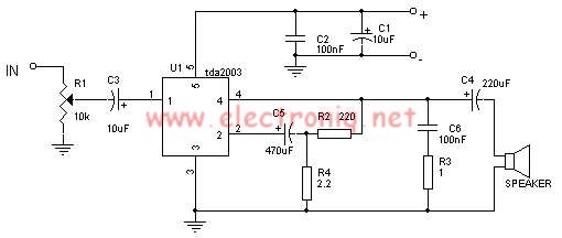
The TDA2003 audio amplifier integrated circuit can be used to design a straightforward 10-watt power audio amplifier for a 2-ohm load or 4 watts for a 4-ohm load. The TDA2003 offers high output current capacity (up to 3.5A) and...
A power amp designed for use in low voltage, especially battery-operated, applications. For minimum parts count, C1 and C2 can be omitted. More: With pins 1 and 8 open circuit the gain in internally set to 20 dB. The described...
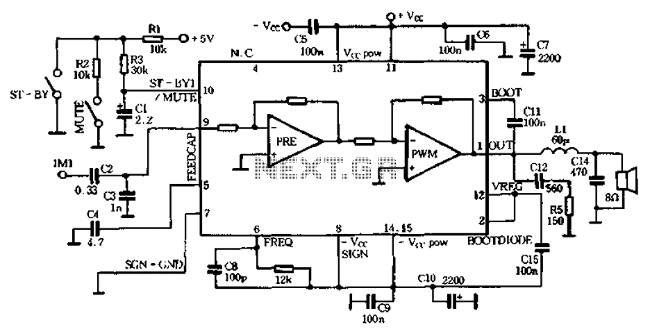
The PWM Class D audio amplifier has been the subject of exploration and reporting for over half a century. This technology is particularly attractive due to its high output efficiency, typically exceeding 85 to 90%. High output efficiency is...
Warning: include(partials/cookie-banner.php): Failed to open stream: Permission denied in /var/www/html/nextgr/view-circuit.php on line 713
Warning: include(): Failed opening 'partials/cookie-banner.php' for inclusion (include_path='.:/usr/share/php') in /var/www/html/nextgr/view-circuit.php on line 713