
MOSFET IRF540A circuit
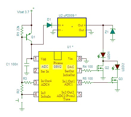
The circuit in question appears to involve a series configuration of light-emitting diodes (LEDs) that require both components to be illuminated for the circuit to be considered complete. This indicates a potential issue in the design or component selection, as typically, series circuits allow for the completion of the circuit with the illumination of a single LED, provided that the current flows through the entire path.
In a standard series LED circuit, when the circuit is powered, current flows through each LED in succession. If one LED fails (open circuit), the entire series circuit will not complete, resulting in both LEDs remaining off. It is essential to ensure that the forward voltage ratings of the LEDs are compatible with the power supply voltage to avoid issues with insufficient voltage across one or both LEDs.
To troubleshoot this circuit, the following steps should be taken:
1. **Check LED Orientation**: Verify that both LEDs are connected in the correct orientation (anode to cathode) to ensure proper current flow.
2. **Measure Voltage**: Use a multimeter to measure the voltage across each LED to confirm that they are receiving the appropriate forward voltage.
3. **Resistor Value**: Ensure that the current-limiting resistor in series with the LEDs is of the correct value to prevent excess current that could damage the LEDs.
4. **Component Integrity**: Test each LED individually to confirm they are functioning correctly. A faulty LED will prevent the circuit from completing, leading to the symptoms described.
5. **Power Supply**: Confirm that the power supply is functioning correctly and providing the required voltage and current for the circuit.
By addressing these aspects, the functionality of the circuit can be restored, allowing for proper operation of the LEDs as intended.Originally Posted by CocaCola His clearly stated his circuit didn`t work correctly, the series was only complete when both LEDs were enabled, not the.. 🔗 External reference
Related Circuits
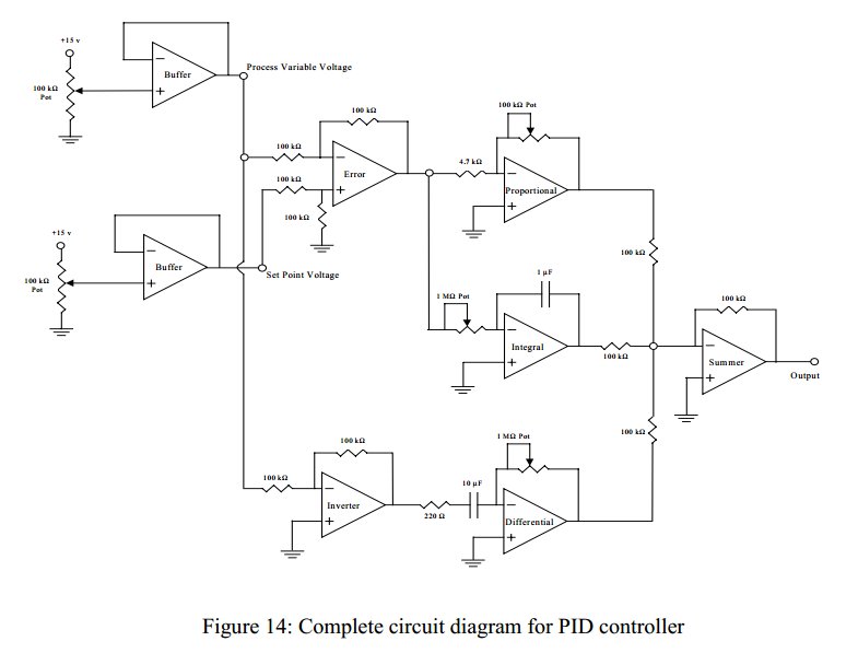
Convert a feedforward operational amplifier PID loop to C code. Assistance is needed for this conversion, as the process is unfamiliar. Input values can be obtained through an ADC, such as voltage or current, but coding a feedforward PID...
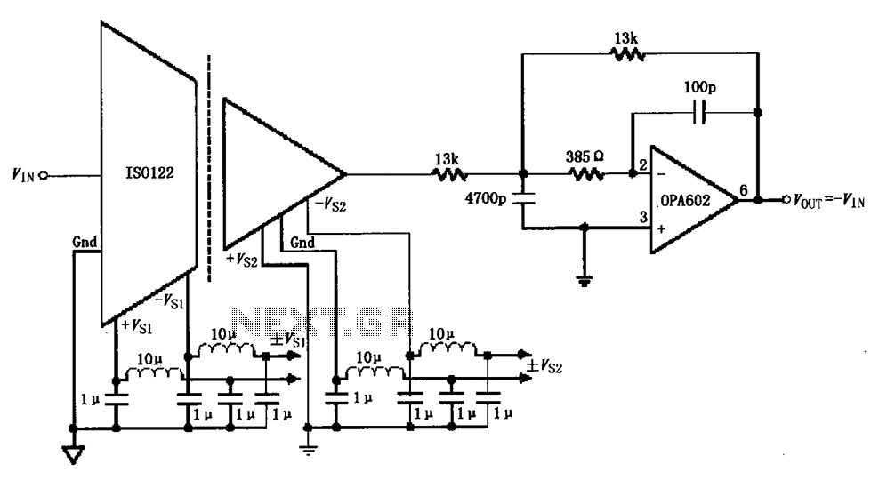
The ISO122/124-type filter circuit is designed to address noise suppression from the DC/DC converter. The internal oscillator frequency of the ISO122/124 modem is set to 500 kHz. The circuit employs inductors and capacitors for filtering to mitigate any beat...
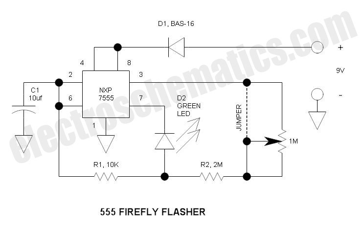
This circuit operates similarly to a standard 555 astable timer, with the distinction that the LED is integrated into the capacitor reset path. Consequently, when pin 7 discharges capacitor C1 to ground, a relatively high current flows through the...
This project involves a straightforward and practical 12V power supply circuit utilizing the LM7812 integrated circuit (IC). The LM7812 is a three-terminal fixed voltage regulator IC housed in a TO-220 package. It incorporates several built-in features such as thermal...
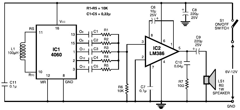
The circuit is built around the popular CMOS oscillator-divider IC 4060 and a small audio amplifier LM386. The IC 4060 functions as a multitone generator. A 100 H inductor is used at the input of the IC 4060, allowing...
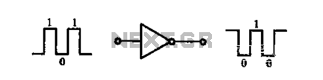
A common-emitter transistor amplifier produces an output signal that is 180 degrees out of phase with the input signal, commonly referred to as an inverting amplifier. When the electrical path for amplifying the pulse signal is activated, this circuit...