
27mhz intercom walkie talkie circuit

The intercom walkie-talkie circuit is a sophisticated integration of components that enables effective voice communication through radio frequencies. The heart of the system is the crystal oscillator, which provides a stable frequency reference essential for both transmitting and receiving audio signals. The use of amplitude modulation allows for the effective transmission of voice without altering the frequency, ensuring clarity and stability in communication.
The four-transistor configuration is particularly noteworthy for its versatility and efficiency. By employing a single design for both transmitting and receiving, the circuit minimizes component count and complexity, making it suitable for compact applications. The addition of the 390-ohm resistor plays a crucial role in transitioning the circuit from a transmitter to a receiver, effectively controlling the gain and sensitivity of the oscillator stage.
The audio amplifier section, formed by the Darlington pair, is designed to provide high gain, ensuring that even weak audio signals can be amplified sufficiently to drive the speaker. This is critical for maintaining audio quality and intelligibility in both modes of operation. The dynamic microphone functionality of the speaker enhances the circuit's dual-use capability, allowing for seamless switching between transmitting and receiving modes.
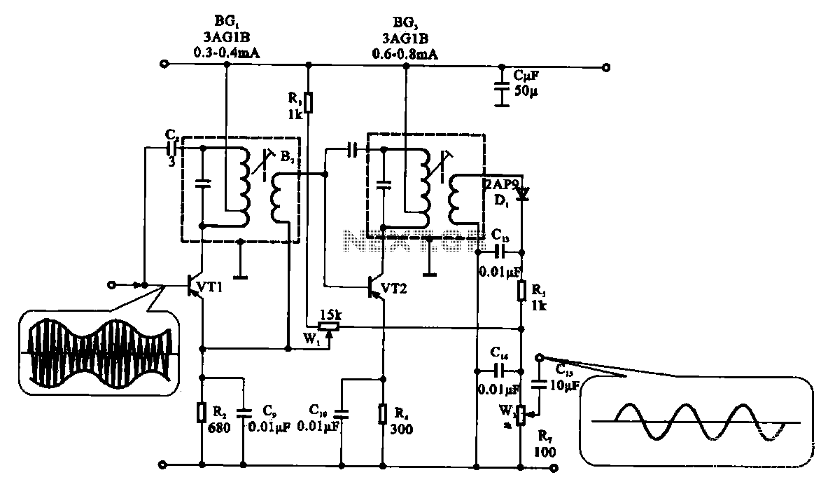
In conclusion, the intercom walkie-talkie circuit exemplifies an efficient design that leverages crystal oscillators and transistor amplifiers to facilitate effective voice communication. Its dual functionality, coupled with a straightforward design, makes it an excellent choice for portable communication devices.Intercom walkie talkie are the next logical step in this discussion. They show how a crystal oscillator can be used to transmit voice. Transmitting a voice via a crystal locked oscillator is not easy. This is because the crystal is locking the frequency and it is very difficult to shift it. The only way to do it is to add the audio as an amplitude component so that the amplitude of the oscillator rises and falls with the audio signal but its frequency does not change. This is the figure of the circuit; Nearly all the components in the 4-transistor circuit are used for both transmitting and receiving.
This makes it a very economical design. The frequency-generating stage only needs the crystal to be removed and it becomes a receiver. The operation of this circuit coincides with our discussion on receiver circuits at the beginning of this article where we said the receiver was oscillating all the time, similar to a weak transmitter. A 390R is added to the emitter of the oscillator stage to reduce the activity and turn it into a receiver.
The next section of the circuit is called a building block. It consists of three transistors directly coupled to produce an audio amplifier with very high gain. The first transistor is a pre-amplifier and the next two are wired as a super-alpha pair, commonly called a Darlington pair to drive the speaker transformer. The third block is the speaker. This is a separate item because it is used as a speaker in the receive mode and a dynamic microphone in the transmit mode.
A speaker can be used in reverse like this and it is called a dynamic microphone because of the coil and magnet arrangement. When you talk into the cone, the movement of the voice coil in the magnetic field produces a few millivolts output.
This can be coupled to a high gain amplifier to get quite good results. When the walkie talkie is in the receive mode, the first transistor is configured as a receiver and the audio is picked off the 4k7 load resistor via a 0. 47u electrolytic. It then passes through a volume control and into the three transistor amplifier. The speaker transformer couples the amplifier to the speaker and we hear the result. When the walkie talkie is in the transmit mode, the speaker is placed at the input of the audio amplifier.
🔗 External reference
Related Circuits
Unfortunately, there is no breadboard available for testing; however, modifications can be made to the PCB. The 1K potentiometer has been removed until the strobe functionality can be established. The circuit in question appears to involve a strobe light mechanism,...
Sur ce site, il est possible de trouver des contributions dans des domaines d'intérêt variés. Il est également possible de suivre l'auteur sur Twitter : @davbucci. Le site est constitué de contributions hétérogènes. L'accès se fait via les liens...
Circuit designed to alleviate concerns related to high frequency utilizes a ready-made module, specifically an Aurel audio FM transmitter. This compact circuit board, measuring 2 cm by 4 cm, supports a modulation frequency track and delivers an RF power...
The demodulation and detection circuit is a radio AM intermediate frequency (IF) signal amplifier that performs two-stage detection using diode Dr. It extracts the audio signal from the IF carrier detection and subsequently sends it to the power amplifier...

This is a water sensor circuit design based on a Conductive Liquid Level Sensor. This single-chip circuit is compact and simple. It is an AC-excited fluid level sensor, which uses alternating current to provide biasing for the sensor probe,...
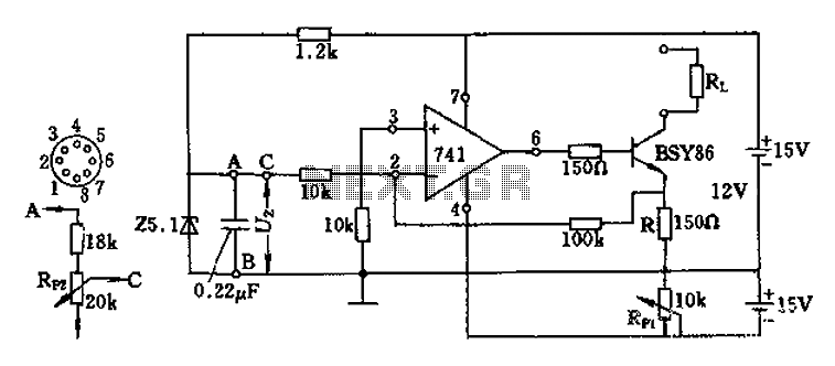
The Darlington transistor circuit BSY86 produces a large output current, with a maximum limit of 150 ohms. The output current is adjustable via resistor R and the RP1 potentiometer, maintaining constancy regardless of the load resistance Rl. The potentiometer...