
28 LED Clock Timer
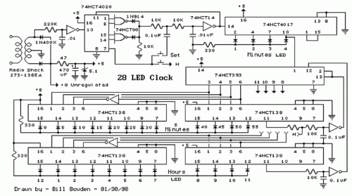
The 4 bits of this counter are then decoded into one of 12 outputs by two 74HCT138 (3 line to 8 line) decoder circuits. The most significant bit is used in conjunction with an inverter to select the appropriate decoder. During the first eight counts, the low state of the MSB is inverted to supply a high level to enable the decoder that drives the first 8 LEDs.
During counts 9 to 12, the MSB will be high and will select the decoder that drives the remaining 4 LEDs while disabling the other decoder. The decoded outputs are low when selected and the 12 LEDs are connected common anode with a 330 ohm current limiting resistor to the 5 volt supply.
The 5th output of the second decoder (pin 11) is used to reset the binary counter so that it counts to 11 and then resets to zero on the 12th count. A high reset level is required for the 393 counters, so the low output from the last decoder stage (pin 11) is inverted with one section of a 74HCT14 hex Schmitt trigger inverter circuit.
A 10K resistor and 0. 1uF cap are used to extend the reset time, ensuring the counter receives a reset signal which is much longer than the minimum time required. The reset signal is also connected to the clock input (pin 13) of the second 4 bit counter (1/2 74HCT393) which advances the hour LEDs and resets on the 12th hour in a similar manner.
Setting the correct time is accomplished with two manual push buttons which feed the Q4 stage (pin 7) of the 4020 counter to the minute and hour reset circuits which advance the counters at 3. 75 counts per second. A slower rate can be obtained by using the Q5 or Q6 stages. For test purposes, you can use Q1 (pin 9) which will advance the minutes at 30 per second. The time interval circuit (shown below the clock) consists of a SET/RESET flipflop made from the two remaining NAND gates (74HCT00).
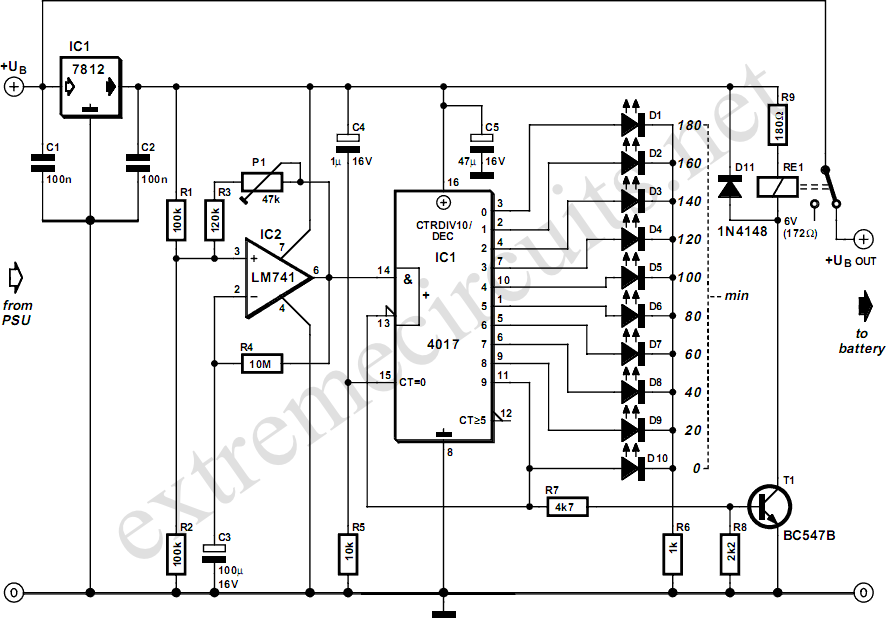
The desired time interval is programmed by connecting the anodes of the six diodes labeled start, stop and AM/PM to the appropriate decoder outputs. For example, to turn the relay on at 7:05AM and turn it off at 8:05AM, you would connect one of the diodes from the start section to the cathode of the LED that represents 7 hours, the second diode to the LED cathode that represents 5 minutes and the third diode to the AM line of the CD4013.
The stop time is programmed in the same manner. Two additional push buttons are used to manually open and close the relay. The low start and stop signals at the common cathode connections are capacitively coupled to the NAND gates so that the manual push buttons can override the 5 minute time duration. That way, you can immediately reset the relay without waiting 5 minutes for the start signal to go away.
The two power supply rectifier diodes are 1N400X variety and the switching diodes are 1N914 or 4148s but any general purpose diodes can be used. 0. 1 uF caps (not shown on schematic) may be needed near the power pins of each IC. All parts should be available from Radio Shack with the exception of the 74HCT4017 decade counter which I didn`t see listed.
You can use either 74HC or 74HCT parts, the only difference between the two is that the input switching levels of the HCT devices are compatible with worst case TTL logic outputs. The HC device inputs are set at 50% of Vcc, so they may not work when driven from marginal TTL logic outputs.
You can use a regular 4017 in place of the 74HCT4017 but the output current will much lower (less than 1 mA) and 4 additional transistors will be required to drive the LEDs. Without the buffer transistors, you can use a 10K resistor in place of the 330 and the LEDs will be visible, but very dim.
We aim to transmit more information by carrying articles. Please send us an E-mail to wanghuali@hqew. net within 15 days if we are involved in the problems of article content, copyright or other problems. We will delete it soon. 🔗 External reference
Related Circuits
Manufacturers of cordless drills typically recommend a battery charging time of three hours. After this time, the battery should be disconnected from the charger to prevent the risk of overcharging. The following circuit is designed to prevent this scenario...
This application note outlines the development and implementation of a Digital Weigh-Scale (DWS) utilizing Zilog's Z8 Encore! Microcontroller. The reference design provides a ready-to-use DWS solution that is easily scalable for measuring high-capacity loads. An external high-resolution Analog-to-Digital Converter...
As equipment becomes increasingly compact, designers are often required to reduce the size of displays. However, this can compromise the usefulness of the display. Many individuals find it challenging to read small displays, which can be particularly frustrating. In...
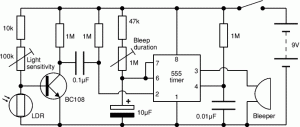
This circuit illustrates the NE555 timer used in a light-sensitive alarm sensor circuit diagram. Features include the ability to detect a sudden shadow falling on the sensor. The NE555 timer is a versatile integrated circuit widely utilized in various timing,...
The BGl and BG2 form a directly coupled amplifier, while BG and BG4 consist of a monostable trigger circuit. Without receiving a prior trigger signal, BG3 enters a saturated conduction state. During this steady state, the collector of BG4...
The NE568A (NE568AD, NE568AN, SA568AD, SA568AN) is a monolithic phase-locked loop (PLL) that operates from 1Hz to frequencies exceeding 150MHz. It features an extended supply voltage range and a lower temperature coefficient of the VCO center frequency compared to...