
universal timer
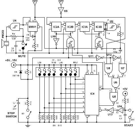
The described circuit is a digital timer that utilizes a binary-coded decimal (BCD) format for setting the time interval via DIP switches. The circuit operates with a 120 Hz input signal, which is derived by doubling the standard line frequency. This signal serves as the primary time reference. The first two integrated circuits (ICs) are responsible for dividing this frequency down to a manageable rate of one pulse per minute, facilitating accurate timing.
The core timing functionality is handled by a third integrated circuit (IC3), which is configured as a countdown timer. This component begins its countdown from the value inputted through the DIP switches and decrements until it reaches zero. The countdown process is initiated by pressing a designated start switch, which also activates a triac. The triac, a type of semiconductor device used for switching and controlling power, remains in the conductive state throughout the countdown period.
Upon reaching zero, the counter triggers an event where the triac is turned off, ceasing its conduction and allowing for a tone to be generated, signaling the end of the countdown. Additionally, the circuit includes a stop button that provides the user with the capability to halt the countdown at any point, adding flexibility and control to the operation of the timer. This feature is particularly useful in applications where precise timing is essential, and the user may need to interrupt the process for any reason.
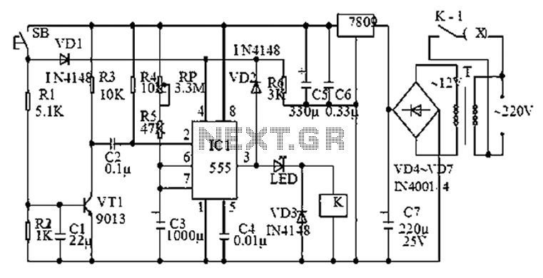
Overall, this circuit design effectively integrates digital control with a straightforward user interface, allowing for versatile applications in timing and control systems.The time interval of this circuit can be varied digitally through the DIP switches. The time code however must be set in BCD form. A 120 Hz signal generated by doubling the line frequency is used as the time reference. This is then divided to 1 pulse per minute by the ICs 1 and 2. The counter IC3 counts backwards- that means it starts to count fro m the value set by the DIP switches going back to zero. Pressing the start switch starts the counter and at the same time the triac is triggered into conduction. Once the counter reaches zero, the triac is switched off and a tone is generated. The stop button offers the possibility of forcibly stopping the counter in the middle of a counting process.
🔗 External reference
Related Circuits
The post discusses a simple delay ON circuit that enables a connected load at the output to be activated with a predetermined delay after the power switch is turned ON. This circuit can be utilized in various applications that...
Speaker relay delay controlling circuit for audio amplifier The speaker relay delay control circuit is designed to protect audio amplifiers and speakers from potential damage caused by inrush current or transient signals during power-up or power-down sequences. This circuit typically...
This circuit illustrates a Go-No/Go Tester Circuit utilizing a 555 Timer IC. Features include a more advanced unit with a precise timed testing procedure. The Go-No/Go Tester Circuit is designed to evaluate components or assemblies by providing a simple pass/fail...
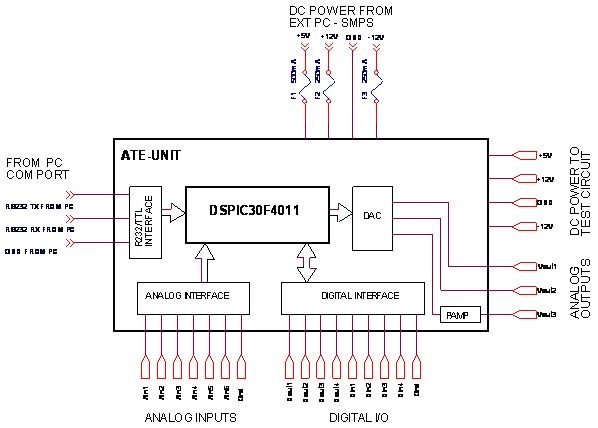
A $35 teaching aid for basic electronics, and an invaluable experimental setup for the electronics hobbyist. It teaches basic analog and digital electronics. The teaching aid is designed to facilitate the understanding of fundamental concepts in both analog and digital...
Q1 and Q2 create an ALL-ON ALL-OFF circuit that, when in the off state, draws negligible current. P1 initiates the circuit, activating the relay and powering the two integrated circuits (ICs). The lamp is energized through the relay switch,...
The 555 timer is commonly used in time-based circuit designs, particularly in monostable configurations. This setup is straightforward and requires only a few resistors and capacitors to achieve triggering. However, external interference can affect the operation of the circuit...
Warning: include(partials/cookie-banner.php): Failed to open stream: Permission denied in /var/www/html/nextgr/view-circuit.php on line 713
Warning: include(): Failed opening 'partials/cookie-banner.php' for inclusion (include_path='.:/usr/share/php') in /var/www/html/nextgr/view-circuit.php on line 713