
28 LED Clock Timers

A 14-stage 74HCT4020 binary counter and two NAND gates are utilized to divide the line frequency by 3600, generating a one-minute pulse that resets the counter and advances the 4017 decade counter. The decade counter counts minutes from 0 to 4 and resets on the fifth count or every 5 minutes, advancing one section of a dual 4-bit binary counter (74HCT393). The four bits of this counter are decoded into one of 12 outputs using two 74HCT138 (3-line to 8-line) decoder circuits. The most significant bit (MSB) is used with an inverter to select the appropriate decoder. During the first eight counts, the low state of the MSB is inverted to enable the decoder driving the first 8 LEDs. For counts 9 to 12, the MSB will be high, selecting the decoder that drives the remaining 4 LEDs while disabling the other decoder. The decoded outputs are low when selected, and the 12 LEDs are connected in a common anode configuration with a 330-ohm current-limiting resistor to the +5-volt supply.
The fifth output of the second decoder (pin 11) resets the binary counter to count to 11 and then resets to zero on the 12th count. A high reset level is necessary for the 393 counters; thus, the low output from the last decoder stage (pin 11) is inverted using one section of a 74HCT14 hex Schmitt trigger inverter circuit. A 10k resistor and a 0.1uF capacitor are used to extend the reset time, ensuring the counter receives a reset signal that exceeds the minimum required duration. The reset signal is also connected to the clock input (pin 13) of the second 4-bit counter (1/2 74HCT393), which advances the hour LEDs and resets at the 12th hour in a similar manner.
Setting the correct time is facilitated by two manual push buttons that feed the Q4 stage (pin 7) of the 4020 counter to the minute and hour reset circuits, advancing the counters at 3.75 counts per second. A slower rate can be achieved by using the Q5 or Q6 stages, while for testing purposes, Q1 (pin 9) can be used to advance the minutes at 30 counts per second.
The time interval circuit, located below the clock, consists of a SET/RESET flip-flop constructed from the two remaining NAND gates (74HCT00). The desired time interval is programmed by connecting the anodes of six diodes labeled start, stop, and AM/PM to the appropriate decoder outputs. For instance, to activate the relay at 7:05 AM and deactivate it at 8:05 AM, one diode from the start section would connect to the cathode of the LED representing 7 hours, the second diode to the LED cathode representing 5 minutes, and the third diode to the AM line of the CD4013. The stop time is programmed similarly. Two additional push buttons allow for the manual opening and closing of the relay. The low start and stop signals at the common cathode connections are capacitively coupled to the NAND gates, enabling the manual push buttons to override the 5-minute time duration, allowing for immediate relay reset without waiting for the 5-minute start signal to clear.
The power supply employs rectifier diodes of the 1N400X variety, while switching diodes may include 1N914 or 4148 types, although any general-purpose diodes may be utilized. The circuit's design ensures reliable timing and control through the combination of digital counters, decoders, and manual overrides, making it suitable for various programmable applications.This is a programmable clock timer circuit that uses individual LEDs to indicate hours and minutes. 12 LEDs can be arranged in a circle to represent the 12 hours of a clock face and an additional 12 LEDs can be arranged in an outer circle to indicate 5 minute intervals within the hour. 4 additional LEDs are used to indicate 1 to 4 minutes of time within each 5 minute interval. The circuit is powered from a small 12. 6 volt center tapped line transformer and the 60 cycle line frequency is used for the time base. The transformer is connected in a full wave, center tapped configuration which produces about 8. 5 volts unregulated DC. A 47 ohm resistor and 5. 1 volt, 1 watt zener regulate the supply for the 74HCT circuits. A 14 stage 74HCT4020 binary counter and two NAND gates are used to divide the line frequency by 3600 producing a one minute pulse which is used to reset the counter and advance the 4017 decade counter. The decade counter counts the minutes from 0 to 4 and resets on the fifth count or every 5 minutes which advances one section of a dual 4 bit binary counter (74HCT393).
The 4 bits of this counter are then decoded into one of 12 outputs by two 74HCT138 (3 line to 8 line) decoder circuits. The most significant bit is used in conjunction with an inverter to select the appropriate decoder. During the first eight counts, the low state of the MSB is inverted to supply a high level to enable the decoder that drives the first 8 LEDs.
During counts 9 to 12, the MSB will be high and will select the decoder that drives the remaining 4 LEDs while disabling the other decoder. The decoded outputs are low when selected and the 12 LEDs are connected common anode with a 330 ohm current limiting resistor to the +5 volt supply.
The 5th output of the second decoder (pin 11) is used to reset the binary counter so that it counts to 11 and then resets to zero on the 12th count. A high reset level is required for the 393 counters, so the low output from the last decoder stage (pin 11) is inverted with one section of a 74HCT14 hex Schmitt trigger inverter circuit.
A 10K resistor and 0. 1uF cap are used to extend the reset time, ensuring the counter receives a reset signal which is much longer than the minimum time required. The reset signal is also connected to the clock input (pin 13) of the second 4 bit counter (1/2 74HCT393) which advances the hour LEDs and resets on the 12th hour in a similar manner.
Setting the correct time is accomplished with two manual push buttons which feed the Q4 stage (pin 7) of the 4020 counter to the minute and hour reset circuits which advance the counters at 3. 75 counts per second. A slower rate can be obtained by using the Q5 or Q6 stages. For test purposes, you can use Q1 (pin 9) which will advance the minutes at 30 per second. The time interval circuit (shown below the clock) consists of a SET/RESET flipflop made from the two remaining NAND gates (74HCT00).
The desired time interval is programmed by connecting the anodes of the six diodes labeled start, stop and AM/PM to the appropriate decoder outputs. For example, to turn the relay on at 7:05AM and turn it off at 8:05AM, you would connect one of the diodes from the start section to the cathode of the LED that represents 7 hours, the second diode to the LED cathode that represents 5 minutes and the third diode to the AM line of the CD4013.
The stop time is programmed in the same manner. Two additional push buttons are used to manually open and close the relay. The low start and stop signals at the common cathode connections are capacitively coupled to the NAND gates so that the manual push buttons can override the 5 minute time duration. That way, you can immediately reset the relay without waiting 5 minutes for the start signal to go away.
The two power supply rectifier diodes are 1N400X variety and the switching diodes are 1N914 or 4148s but any general purpose diodes can be used. 0. 1 u 🔗 External reference
Related Circuits
Switching to alternative power sources can lead to savings on electricity bills. The photovoltaic module or solar panel discussed here has a power output of 5 watts. Under full sunlight conditions, the solar panel generates 16.5V and can provide...
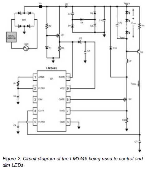
LEDs react much faster than conventional bulbs. Light dimmers for standard bulb-based lighting have been in use for many years. The most common implementation of such dimmers... LEDs, or Light Emitting Diodes, are semiconductor devices that emit light when an...
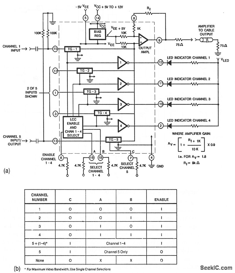
This circuit illustrates a CA3256 switch/amplifier configured for a direct-coupled output. One of four channels can be selected in parallel with channel 5. The analog switches of channels 1 to 4 are digitally controlled by logic. A VEE of...
This oscilloscope clock project utilizes a PIC 16F876 microcontroller and a digital-to-analog converter (DAC) to generate X and Y signals for displaying a clock on an oscilloscope. The original circuit and software were designed by OZ2CPU. The clock circuit...
I needed a pulsating light for a certain signaling. Voltage was 230V. So I decided to make a simple circuit, consisted of a LED diode, two capacitors, two resistors, a diac and a diode. Activity of the circuit is...

This LED VU Meter (volume unit) is designed to monitor and display power levels present at the speaker terminals of a stereo audio power amplifier. The levels are represented in ten discrete steps using ten LEDs for each channel,...