
led vu meter circuit using lm3915 ic

The LED VU Meter circuit operates by utilizing a combination of resistive voltage dividers and voltage comparators to create a visual representation of audio power levels. The primary function of the external resistors R2 and R3 is to establish the reference voltage range for the LED indicators. By adjusting these resistors, the user can calibrate the meter to respond to different input voltage levels, thereby allowing for flexibility in various audio applications.
The integrated circuit's internal architecture is crucial for its performance. The ten comparators are designed to compare the incoming audio signal against predefined voltage thresholds set by the voltage divider. As the audio signal fluctuates, the comparators activate corresponding LEDs based on the signal's amplitude. This results in a dynamic visual display that reflects the audio output in real time.
The high-impedance input buffer is essential for ensuring that the audio signal is not loaded down by the circuit, preserving the integrity of the input signal. This design choice allows the VU Meter to function effectively with a wide range of audio sources, from low-level signals to higher power outputs.
In summary, the LED VU Meter is an effective tool for visualizing audio power levels in stereo amplifiers. Its design incorporates a precise reference voltage, adjustable scaling resistors, and a robust comparator network, making it a versatile solution for audio monitoring applications.This LED VU Meter (volume-unit) is capable of monitoring and displaying power levels present at the speaker terminals of an stereo audio power amplifier. The levels are displayed in ten discrete steps using 10 LEDs for each channel. This project is designed to give an approximate visual indication of the audio power output of each channel.
This is the figure of the circuit; Two external resistors (R2 & R3) programs the full scale from between 1. 2V and 12V applied to pin 5. 10. 5V is used to turn on all 10 LED`s. The voltage required to turn on all the LEDs is set by R2 and R3. The IC develops a nominal 1. 25V reference voltage (Vref) across pins 7 and 8. Since this voltage is constant then the current through R3 is also constant. This current also flows through R2. The total voltage across R2 and R3 is given by voltage. Internally this chip consists of ten voltage comparators. The non-inverting (+) input of each comparator is connected to an accurate ten-step voltage divider network. Each comparator will therefore trigger on a different comparison level. The inverting (-) inputs of each comparator are commoned together and connected to an incoming DC signal via a high impedance input buffer.
🔗 External reference
Related Circuits
All car batteries require a 12V battery charger, which also applies to marine, RV, and power sports batteries. The high-efficiency lead-acid batteries available today necessitate more effective charging techniques. The battery charger is a crucial tool for prolonging battery...

To utilize this facility, the calling subscriber must first dial the standard phone number of the intended recipient. Once the call is connected, the calling party does not hear a ring-back tone. The calling subscriber must then press the...
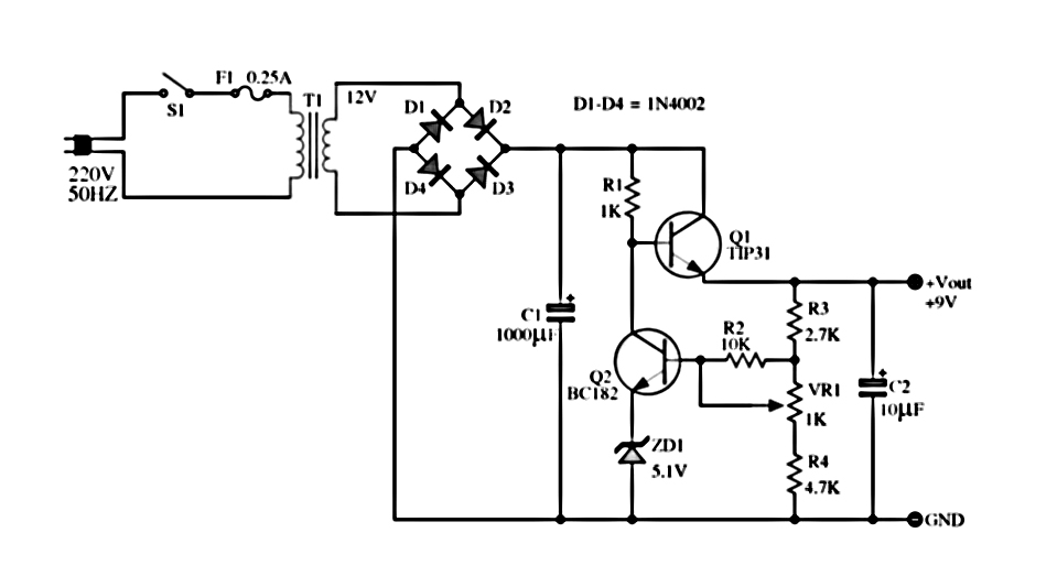
The power supply described utilizes a regulator composed of two NPN transistors. One transistor functions as the power regulator, while the other controls the output voltage. This power supply offers an adjustable output voltage range of 6-12 VDC. The...
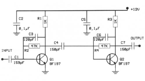
The following circuit illustrates a 20 dB VHF amplifier circuit diagram utilizing the BF197 transistor. Features include a simple circuit design. The 20 dB VHF amplifier circuit is designed to amplify very high frequency signals, making it suitable for applications...
This is a simple proximity switch utilizing the IC 4049. The IC 4049 is a bipolar monolithic integrated circuit designed for metal detection systems and proximity sensing applications. It includes an oscillator formed by an external parallel resonant tank...
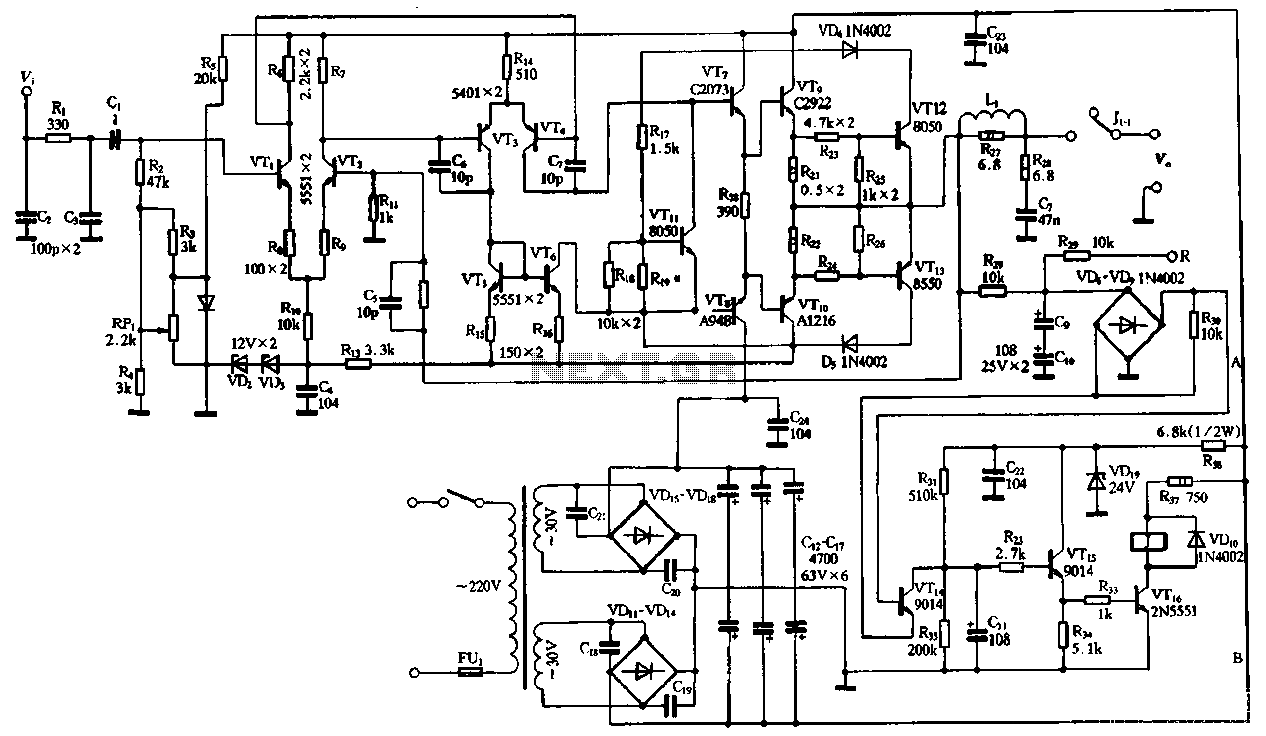
The performance of the amplifiers 2SC2922 and 2SA1216 (or 2SC3264 and 2SA1295) is excellent, featuring good linearity and strong overload capabilities. These devices are utilized as high-fidelity power amplifier stages, demonstrating outstanding performance. The circuit, as illustrated in Figure...