
Oscilloscope Clocks
This oscilloscope clock project represents a unique integration of microcontroller technology and analog circuitry to create a functional and visually appealing timekeeping device. The use of the PIC 16F876 microcontroller allows for precise control over the timing and display of the clock, while the DAC generates the necessary analog signals for the X and Y axes on the oscilloscope. The choice of a 12VAC wall adapter ensures a stable power supply, and the inclusion of a current-limiting resistor enhances circuit safety.
The design's flexibility is evident in its compatibility with various oscilloscope types, including vintage vacuum tube models. The ability to omit the blanking signal further broadens its usability, allowing for simpler oscilloscopes to display the clock without additional circuitry. The dual-switch mechanism for time setting adds an interactive element to the project, although further documentation could clarify their respective functions.
The project also highlights the importance of component selection, particularly regarding the crystal frequency. While a 19MHz crystal is recommended for optimal performance, the successful use of a 16MHz crystal demonstrates the project's adaptability. The exploration of different oscilloscopes, including the Bell & Howell and Supreme models, showcases the versatility of the design and its potential for educational demonstrations or hobbyist experimentation.
Overall, this oscilloscope clock project is a well-thought-out amalgamation of modern microcontroller applications and classic analog technology, making it an intriguing subject for both electronics enthusiasts and professionals alike. The schematics provided serve as a valuable resource for those interested in replicating or modifying the design for their own use.This oscilloscope clock project uses a PIC 16F876 and a DAC to generate X and Y signals to draw a clock on the oscilloscope. The original circuit and software was designed by OZ2CPU, which can be found here:. The clock circuit was slightly modified to use a different DAC from Texas Instruments. The 60Hz signal was obtained from the AC side of a 12VAC (NOT DC) wall adapter and the current is limited with a 10K resistor. Below is the schematic of the minimal oscilloscope clock circuit: At first I didn`t bother building the entire oscilloscope from scratch because I had a handful of oscilloscopes sitting around. However, the only working oscilloscope I had with a Z axis input was the Tektronix 7704A, but experiments showed that the blanking signal from pin 26 of the PIC was not entirely necessary.
The blanking is only used to supress any lines from appearing while the DAC quickly changes from a point to another point. It turns out that the vectors are drawn so quickly that there is almost nothing visible between points without the blanking signal.
Omitting the use of the blanking signal makes this circuit more versatile for a wide range of oscilloscopes with simple X and Y inputs, including vacuum tube oscilloscopes! However, the graphics are stable and crisp with DC coupling to the oscilloscope. Most tube scopes use AC coupling, but if the deflection amplifiers are designed well then the graphics will look pretty good.
The only downfall with AC coupling is a degree of image distortion and the image will drift around the CRT face, but the benefit of the drifting is a reduced risk of phosphor burn on the screen. The two switches (SW1 and SW2) sets the time, but I`m not sure which switch does what so you`ll have to find out.
One switch will change the clock mode which includes Run, Hours Set, and Minutes Set. The other switch will change the digits for the time set modes. The HEX file for the program I used is here: scopeclock60hz. hex. Note that Thomas (OZ2CPU) wrote the clock program and did not provide the. ASM file. The 50Hz version can be found on his scope clock webpage (link provided above). Note that the original crystal frequency specified by Thomas for the 60Hz version of the scope clock is 19MHz, but I had success using a 16MHz crystal for version 1 because that crystal was what I had on hand at the time. The 60Hz line frequency maintains the timekeeping, so crystal speed is not terribly important. However, a higher frequency crystal will provide better graphics refresh rates. The oscilloscope clock on the Bell & Howell 34 tube oscilloscope. Note that I had to flip the photograph upside-down because the oscilloscope`s Y plates are inverted. On the solid-state Bell & Howell. Here both the X and Y plates are inverted, so the photograph had to be flipped in both directions. I eventually reversed the X and Y plates to fix this problem. On the 1930`s Supreme 546 tube oscilloscope. This is my favorite oscilloscope for demonstrating the clock because the image looks pretty good on the 3AP1 CRT.
Later on I decided to make a dedicated scope clock and had a design for a simple three tube oscilloscope using a 6BC7 and a pair of 6AU6 tubes. It is nice to add a little of nostalgia to the clock by using an all-tube oscilloscope. I experimented with the circuit used in the Ultra-Simple Oscilloscope but avoided using a large power transformer by using the 6BC7 as a voltage tripler to provide the B+ supply.
Moreover, a filament transformer for the tube filaments were also avoided by using a series circuit. Below is the schematic of the three tube XY oscilloscope using the 2AP1 CRT. The 6BC7 tripler provides about 400VDC loaded, which is sufficient for the 2AP1 CRT and the 6AU6 deflection amplifiers. Later experimentation found that if the B+ was lowered to about 300VDC, the clock display on the CRT will grow larger but dimmer.
However, with a lower B+ the oscilloscope needs 🔗 External reference
Related Circuits
The oscilloscope remains one of the most essential measurement tools for electronic engineers. With the introduction of reasonably priced USB oscilloscopes, this instrument has become accessible to a wider audience. Twenty-five years ago, however, a quality oscilloscope was an...
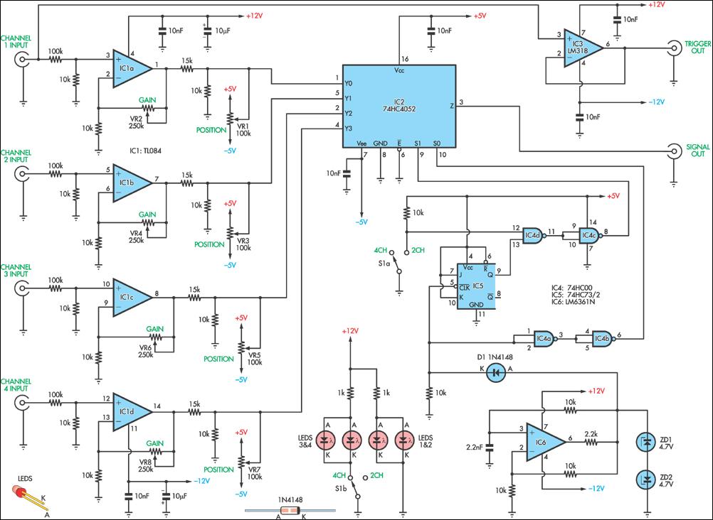
This circuit allows the simultaneous display of four signals using only one channel of an oscilloscope. It sequentially switches each input to the output while performing some signal conditioning. This configuration is designed for low-frequency signal measurements and lacks...
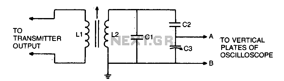
To display an RF signal, connect LI to the transmitter and points A and B to the vertical plates of the oscilloscope. Adjust LI for minimum SWR and C3 for the desired trace height on the CRT. More: L2...
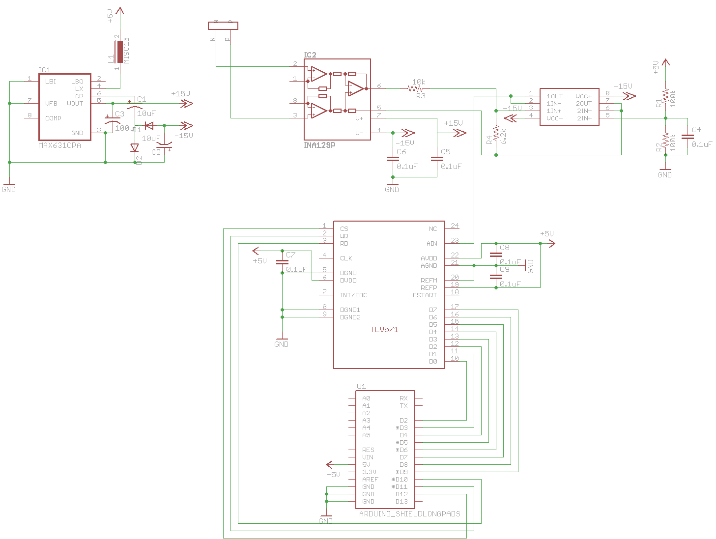
A digital oscilloscope is being developed using Arduino, designed as an Arduino Shield. The current implementation functions but exhibits signal distortions. A TLV571 chip is utilized in the design. The project involves creating a digital oscilloscope that can be mounted...
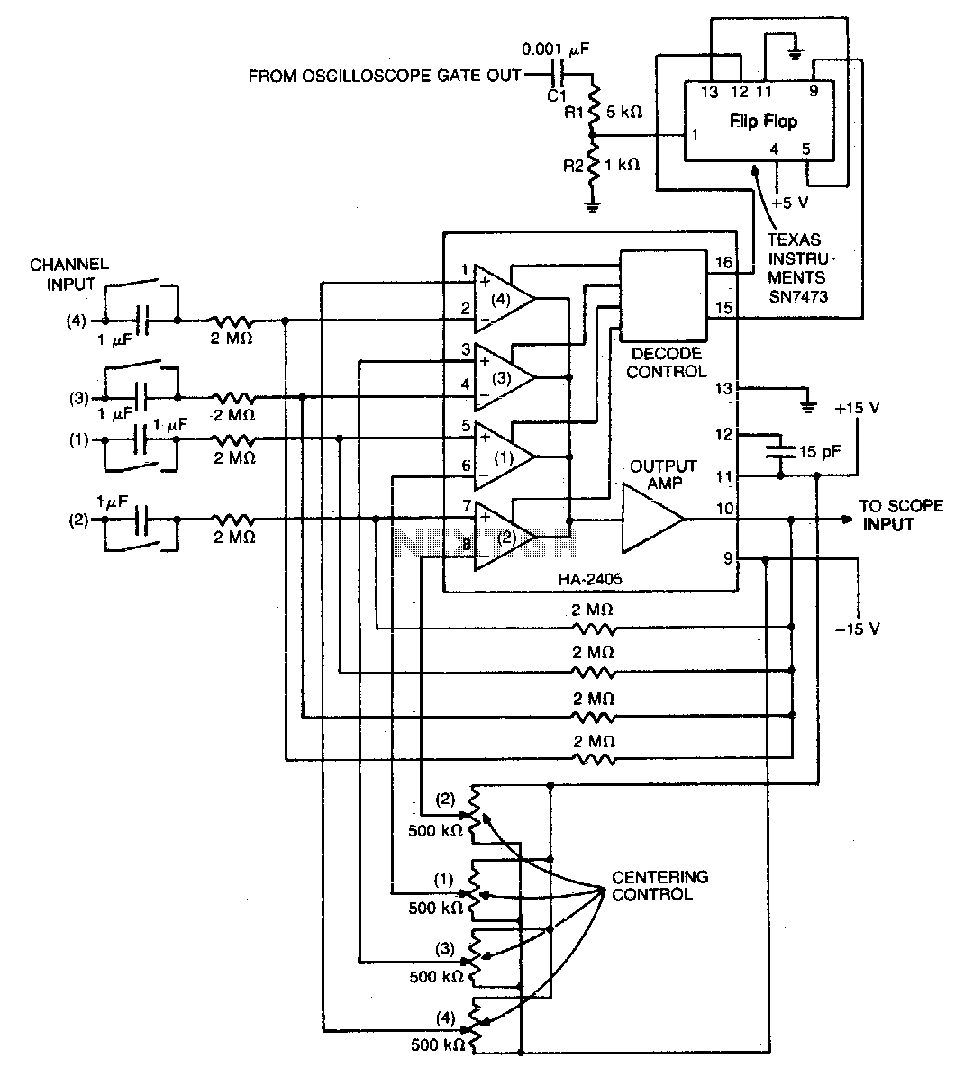
The monolithic quad operational amplifier offers a cost-effective solution for enhancing the display capabilities of a standard oscilloscope. Binary inputs control the integrated circuit operational amplifier, while a dual flip-flop divides the oscilloscope's gate output to generate channel selection...
For this project, digital signals can be communicated with computers, while analog signals cannot. RS232 refers to the serial port located at the back of the computer, which has multiple ports for connecting devices. The RS232 port has 9...