
2Mhz Frequency Counter Circuit
The 2-MHz frequency counter circuit is designed to accurately measure and display frequency signals up to 2 MHz. The core of the design is the ICM7224IPL, which integrates both the counter functionality and the display driver, facilitating a streamlined architecture that reduces component count and complexity. The LCD-004 display is utilized for visual output, allowing users to easily read the frequency measurements.
The signal amplification stage is critical for ensuring the input signal is adequately processed. Transistors Q2 and Q3 are configured as a differential amplifier to enhance the input signal's amplitude, improving the overall sensitivity of the frequency counter. This is particularly important in applications where the input signal may be weak or subject to noise.
The crystal oscillator, consisting of U3-c and XTAL1, serves as the timing backbone of the circuit. It generates a stable frequency reference that is essential for accurate counting. The crystal's frequency stability ensures that the measurements taken by the counter are precise and reliable. The oscillator output is then divided by two stages, creating multiple timing references. This feature allows for flexibility in measurement, as users can select among three different timing references according to their specific requirements.
The logic chips incorporated into the circuit are responsible for managing the timing pulse circuitry, coordinating the operation of the counter, and ensuring that the display driver receives the correct signals to present the frequency reading. The design emphasizes modularity, enabling easy upgrades or modifications to accommodate future enhancements or changes in application needs.
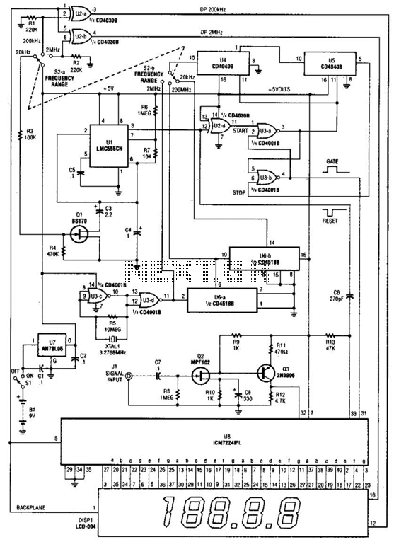
Overall, this frequency counter schematic represents a well-thought-out design that combines essential components to achieve accurate frequency measurement and display, making it suitable for a variety of electronic applications. This is a schematic and block diagram of a 2-MHz frequency counter. It uses and LSI counter/display driver, LCD readout, and a few logic chips for timebase and timing pulse circuitry. Q2 and Q3 form a signal (input) amplifier. The circuit contains a crystal oscillator built around U3- c and XTAL1, which provides the primary timing-reference signal.
That signal is then divided twice to provide two additional timing references, giving the circuitry three selectable timing references. The ICM7224IPL is an integrated circuit that consists of the counter and display driver to drive the LCD-004 display. 🔗 External reference
Related Circuits
The wireless calling device consists of a calling unit and a host. These two components communicate using a DTMF encoder pulse. Each calling unit is assigned a unique code, although the circuits are identical. The calling unit is depicted...
A microprocessor cannot drive a motor directly since it cannot supply enough current. Instead, an interface circuit is required so that the motor power is supplied from another source, with only control signals derived from the microprocessor. This interface...
Activated this and inadvertently destroyed several 2N3055 transistors by shorting the emitters to ground. In all cases, the transistors opened up, and no damage to the emitter occurred in any transistor. The alternative circuit in Figure 2 will provide...

This design circuit serves as a converter utilizing the LM2623A ratio adaptive circuit to drive a digital camera motor. It generates 5 volts from input voltages that range between 1.8 and 4.5 volts. The circuit's duty cycle, while not...
This circuit generates a sound similar to that of ambulance sirens. It differs from typical ambulance siren circuits in its design. The circuit utilizes a combination of oscillators and amplifiers to produce a sound that mimics the varying pitch and...
It is a wireless doorbell with a cost of about $10.00. This product encourages a shift in approach to building projects, utilizing such items to learn about their functions and modify them to meet specific needs. The doorbell incorporates...