
2Mhz oscillator
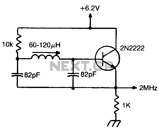
The Miller 9055 miniature slug-tuned coil is designed for applications requiring precise tuning and compact form factors. This coil is characterized by its miniature size, allowing it to be integrated into various electronic circuits where space is limited. The slug-tuned feature enables fine adjustments to the inductance, which is crucial for optimizing circuit performance in RF applications, such as oscillators, filters, and amplifiers.
All resistors in the circuit are specified to be 1/4W with a tolerance of 5%. This ensures that the resistors can handle the power levels typically encountered in such applications while maintaining a reasonable level of accuracy in their resistance values. The choice of 5% tolerance allows for cost-effective components while still meeting the performance requirements for most applications.
The capacitors utilized in the circuit are specified as a minimum of 25 V ceramic capacitors. Ceramic capacitors are known for their stability, low leakage, and high-frequency performance, making them suitable for RF applications. The 25 V rating indicates the maximum voltage that the capacitors can safely handle, providing a margin of safety for circuit operation.
Overall, the combination of the Miller 9055 coil, 1/4W resistors, and 25 V ceramic capacitors creates a reliable and efficient circuit design suitable for various electronic applications where size and performance are critical.Miller 9055 miniature slugtuned coil; all resistors 1/4W 5%; all caps min 25 V ceramic. 🔗 External reference
Related Circuits

This circuit is a voltage-controlled oscillator (VCO) that utilizes the 555 timer integrated circuit (IC) as its primary component. The 555 timer is configured as an astable multivibrator, enabling it to function as an oscillator. An astable multivibrator is...

This circuit represents a negative resistance configuration. All previous circuits utilize RC time constants to achieve resonance. LC combinations can also be employed, providing good frequency stability, high Q factor, and rapid startup. In this circuit, a signal input...
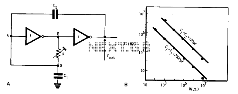
This simple, low-cost oscillator is constructed using two CMOS buffer inverters, two capacitors, and a variable resistor. The circuit operates with voltage levels ranging from 4 V to 18 V. When C1 equals C2, the frequency of oscillation is...
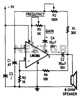
The circuit's frequency oscillation is given by the formula f = 2.8 / [Cix(i1 + i2)]. By utilizing the specified values, the output frequency can be adjusted from 60 Hz to 20 kHz by rotating potentiometer R2. A portion...
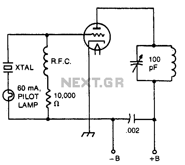
The pilot lamp limits current to prevent damage to the crystal. A very useful circuit. The circuit incorporates a pilot lamp designed to limit the current flowing to a crystal component, thereby safeguarding it from potential damage due to excessive...
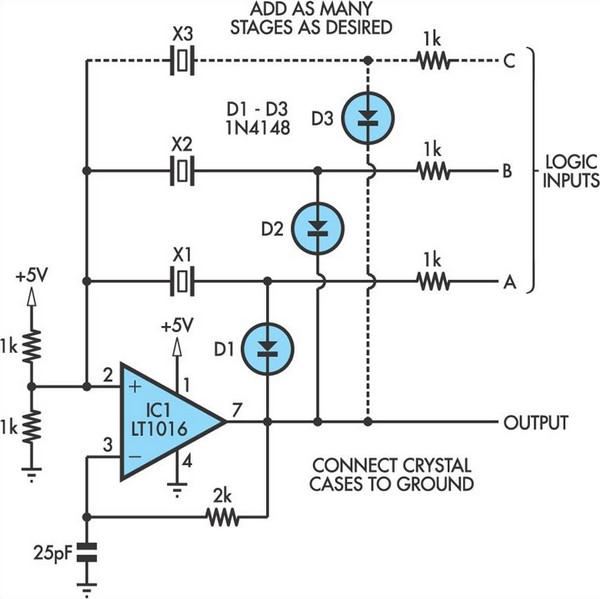
This oscillator circuit allows crystals to be electronically switched through logic commands. The circuit is best comprehended by initially disregarding all crystal components. The oscillator circuit described functions as a frequency generator that utilizes the properties of quartz crystals to...
Warning: include(partials/cookie-banner.php): Failed to open stream: Permission denied in /var/www/html/nextgr/view-circuit.php on line 713
Warning: include(): Failed opening 'partials/cookie-banner.php' for inclusion (include_path='.:/usr/share/php') in /var/www/html/nextgr/view-circuit.php on line 713