
Interfacing 16x2 LCD with 8051 microcontroller. LCD module theory circuit diagram and program in assembly language

The integration of a 16x2 alphanumeric LCD module with the AT89S51 microcontroller involves several key components and steps to ensure proper operation. The JHD162 LCD module typically features a 16-character by 2-line display, making it suitable for various applications that require textual output.
The circuit design includes a connection between the microcontroller and the LCD module, where the microcontroller sends commands and data to control the display. The JHD162 LCD has a specific pinout that includes power supply pins (VSS, VDD), a contrast adjustment pin (V0), and data pins (D0-D7) for 8-bit communication, along with control pins such as RS (Register Select), RW (Read/Write), and E (Enable).
The microcontroller AT89S51, which is an 8-bit microcontroller from the 8051 family, is programmed to interface with the LCD. The program typically initializes the LCD, sets the mode of operation, and sends characters to be displayed. The initialization sequence involves configuring the data pins and control signals, ensuring the LCD is set to 8-bit mode, and setting the cursor position for displaying text.
The schematic diagram illustrates the connections between the AT89S51 and the JHD162 LCD module. It shows how the microcontroller's output pins are connected to the LCD's data and control pins, along with the necessary power supply connections.
In summary, the interfacing of a 16x2 alphanumeric LCD module with the AT89S51 microcontroller encompasses a well-defined circuit design, an understanding of the LCD's pinout and command set, and a programmed microcontroller to manage the display of textual information effectively.Interfacing 16x2 alphanumeric LCD module with AT89S51 microcontroler. Circuit diagram,theory and program. JHD162 lcd module pinout and commands.. 🔗 External reference
Related Circuits
The adjustment control for the contrast of an LC-Display typically utilizes a 10-kilohm potentiometer. This arrangement functions adequately, provided that the power supply voltage remains constant. However, in situations where the power supply is variable, such as with a...
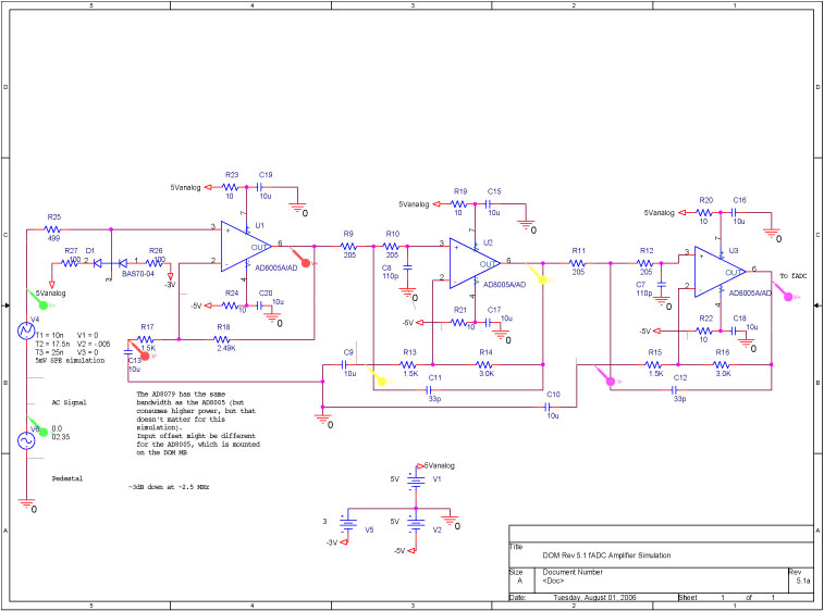
A bandwidth-limited amplifier shapes the waveform sampled by the 40 MHz high-speed pipeline Analog to Digital Converter (fast ADC, or fADC). It is well known that the shaping time is twice the time constant (peaking time) for each pole...
The figures (a) and (b) illustrate AC measuring circuits. Figure 21(a) presents a current measuring schematic diagram utilizing a magnetic balanced mode Hall device. When the magnetic field generated by the measured current, denoted as IN, is B1, this...
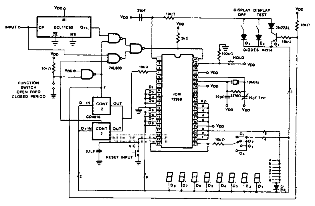
A CD4016 analog instrument is utilized as a multiplexed digital output, transferring the output function back to the input. The CD4016 operates as a digitally controlled analog transmission gate, eliminating the need for a digital output level shift. Alternatives...
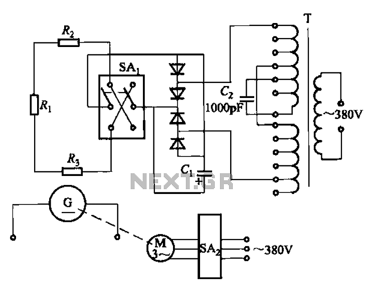
The AR-300 DC arc welding machine circuit includes the AX, AX1, AX3, and AR series. The structure of these machines is fundamentally similar, consisting of a three-integral unit converter, a phase asynchronous motor, and a DC arc welding generator...
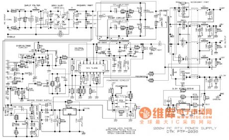
This example presents a switch DC regulated power supply circuit designed for buck-mode +5V applications. It consists of a power supply circuit, an impulsator, a voltage sampling or pulse width modulation circuit, and a buffering driver circuit, as illustrated...