
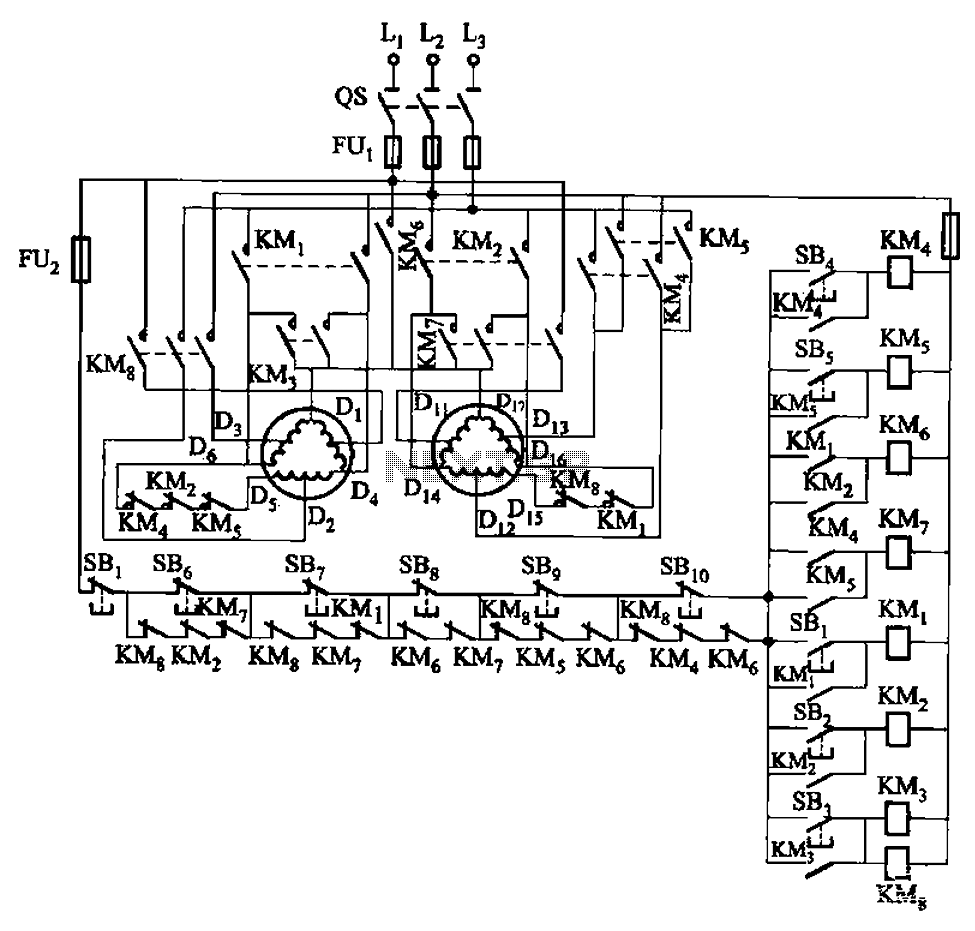
2Y-Y-2 - connection four-speed motor contactor control circuit
This circuit design is aimed at providing efficient control over a small motor while ensuring safety and operational flexibility. The use of an intermediate relay instead of a contactor simplifies the circuit when dealing with lower power requirements, reducing both cost and complexity.
The four-speed forward and one-speed reverse operation is achieved through a series of push buttons (SB1 to SB10) that are wired to control the motor's speed settings. Each button corresponds to a specific speed, allowing for quick adjustments based on operational needs. The interlocking feature is critical; it prevents two speeds from being activated simultaneously, which could lead to system malfunctions or damage. This is accomplished by using normally closed contacts that open when one speed is selected, thereby disabling the others.
The design also emphasizes user convenience, as it allows for immediate motor speed selection without prior stopping. This feature is particularly useful in applications requiring rapid adjustments. The ability to maintain operational speed while engaging the start buttons enhances the circuit's functionality, making it suitable for various applications where quick response times are essential.
In summary, the circuit provides a reliable and efficient method for controlling a small motor with multiple speed settings while ensuring safety through interlocking mechanisms. Circuit shown in Figure 3-120. If the motor capacity is small (less than the rated current 5A), it can use an intermediate relay (contact a few more) instead of the contactor. The line can be achieved in four speed forward running and reverse running one of the most high-speed e matter and cause a short circuit through the circuit for interlocking contactor normally closed auxiliary contact, to ensure that the two speeds can not start it. The line allows any start button is pressed, the corresponding speed can be obtained immediately without having to press the stop button in advance, regardless of motor speed also at work.
Figure, SBl and SB6, SB2 and SB7, SB3 and SBs, SB4 and SBa, SBs are linked with SBao button.
Related Circuits
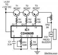
This is a simple home telephone ringtone generator circuit constructed using only a few electronic components. It generates a simulated telephone ringtone and requires a DC supply voltage ranging from 4.5V to 12V. This circuit can be used in...
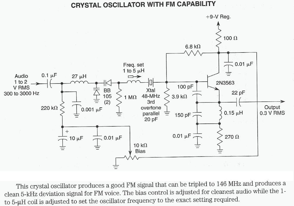
The 7th overtone of 18 MHz (17m) is 144 MHz (2m) directly within the CW region. Icarus is a high-altitude balloon (HAB) project funded by advertising revenue, which has successfully launched numerous balloons that captured impressive photographs. Robert Harrison...
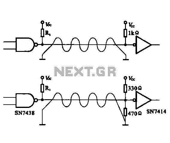
The circuit configuration for data signal output is designed to optimize transmission distance. It includes an output terminal connected to a pull-up resistor at the receiving end, which works in conjunction with two pull-up and pull-down resistors. The described circuit...
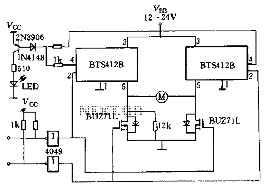
The BTS412B functions as two high-side power MOSFET switches, while two BU271L (50V, Zhang 1n) serve as low-side switches, forming a bi-directional H-bridge DC motor drive circuit. This configuration is designed for electrical automatic door systems, capable of handling...
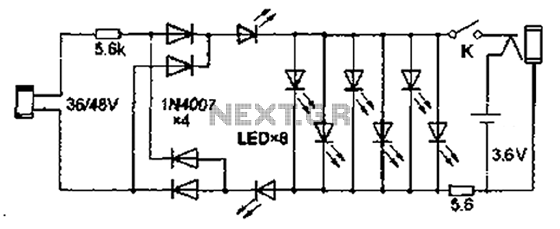
Also known as the Free lamp (commonly referred to as the Myanmar lamp by online sellers), this device operates using the voltage from a standard household fixed telephone line, eliminating the need for batteries or AC power. The lamp...
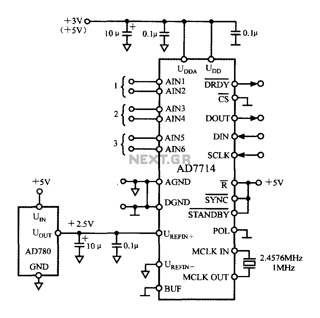
The typical application circuit for the AD7714 is illustrated in the accompanying figure. The UDD and UDDA terminals of the AD7714 can be connected to either a +3V or +5V power supply. The analog inputs are arranged as three...
Warning: include(partials/cookie-banner.php): Failed to open stream: Permission denied in /var/www/html/nextgr/view-circuit.php on line 713
Warning: include(): Failed opening 'partials/cookie-banner.php' for inclusion (include_path='.:/usr/share/php') in /var/www/html/nextgr/view-circuit.php on line 713