
3 band equalizer circuit
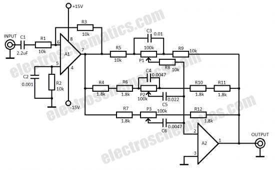
This three-band equalizer circuit is designed to enhance audio signals by allowing the user to adjust the levels of bass, midrange, and treble frequencies independently. The active filter network utilizes the LM833 op-amp, known for its low noise and high performance, making it suitable for audio applications.
The circuit typically includes three separate filter stages, each corresponding to one of the frequency bands. Each stage employs a potentiometer to adjust the gain for that specific frequency range, allowing for precise control over the audio output. The feedback configuration of the op-amp is crucial, as it determines the frequency response and the overall performance of the equalizer.
The DC coupling of the output is beneficial for maintaining signal integrity; however, the potential for DC offsets from the potentiometers necessitates the inclusion of a coupling capacitor to block any unwanted DC components. This ensures that only the AC audio signal is passed to the subsequent stages or output devices.
The equalizer's maximum range of 15 dB provides sufficient headroom to boost or cut frequencies as desired, while the 90 dB noise attenuation at the center position ensures that the audio output remains clean and free from interference. The specified bandwidth of 1 MHz indicates that the circuit can handle a wide range of audio frequencies, making it suitable for high-fidelity applications.
The gain adjustment formula, Vu = R2/R1, allows for further customization of the equalizer's response. By altering R2, the user can modify the gain of the circuit to suit specific audio requirements, enhancing the versatility of the equalizer in various audio processing scenarios. Overall, this three-band equalizer circuit represents an effective tool for audio signal manipulation, providing users with the ability to tailor their sound to their preferences.This 3 band equalizer circuit is an active filter network for bass, mid and high audio ranges. It is designed around the LM833 opamp from National Semiconductors. The output of this 3 way graphic equalizer is designed to be DC coupled, however due to slight DC variations through the 100K potentiometers at the feedback lines of the opamp A2, a coup ling capacitor might be needed. The maximum equalizer range is about 15 dB. In the middle position of potentiometer, the noise attenuation is about 90 dB with a bandwidth of 1 MHz and a gain of 0 dB. The gain can be changed through R2 using the following formula: Vu = R2/R1. 🔗 External reference
Related Circuits
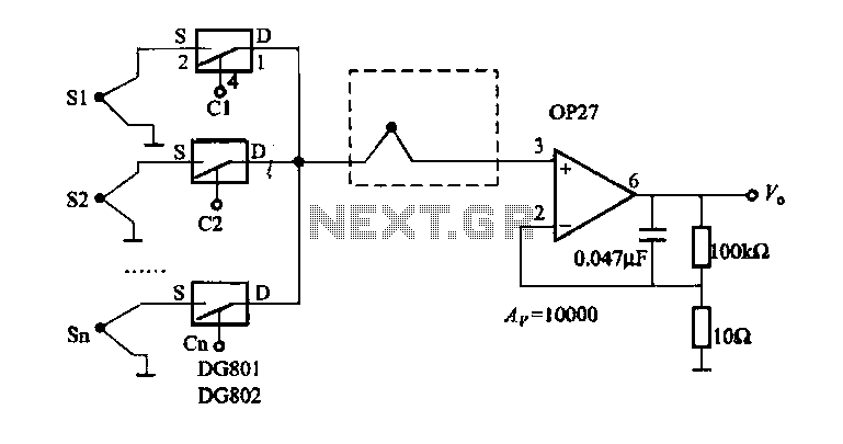
The electronic switch selection allows for multiple temperature control and monitoring points. It utilizes OP27 in conjunction with multiple S-type thermocouple circuits. The DG801/802 ultra-low on-resistance electronic switch has a maximum on-resistance of 0.40 ohms and operates under single-supply...
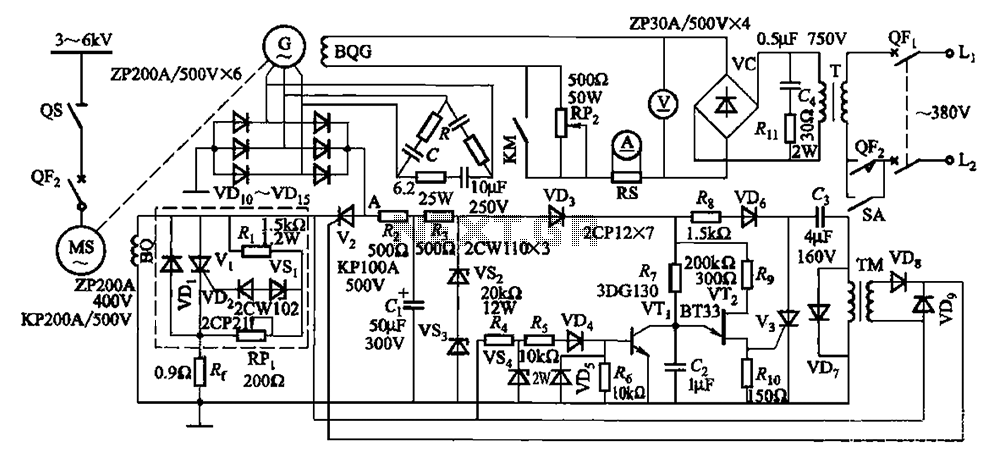
The circuit depicted in Figure 16-105 illustrates a synchronous motor. The components include BQ, which represents its field winding, and G, which denotes the AC excitation for the motor. The notation BQG indicates the field winding, with an empty...
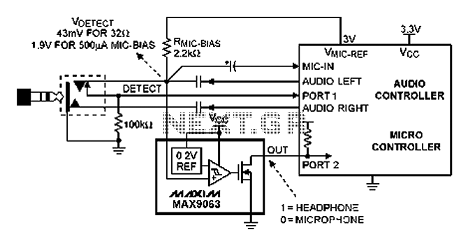
A headphone type detection circuit is illustrated in the attached figure. The 2.2k RMIC-BIAS resistor connected to the audio controller provides a low-noise reference voltage (VMIC-REF). When the audio jack is inserted, the VMIC-REF voltage through RMIC-BIAS is applied...
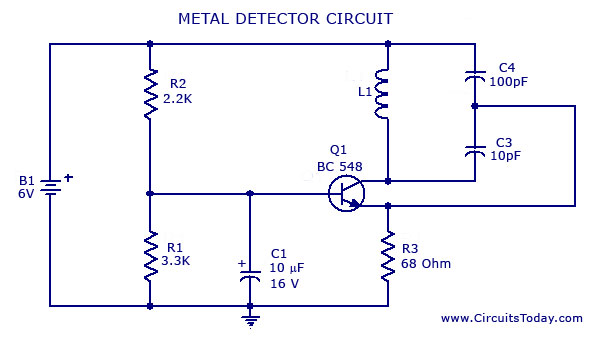
A simple metal detector circuit diagram and schematic using a single transistor and a radio. This metal detector/sensor project is easy to make and is an application of a Colpitts oscillator. The metal detector circuit utilizes a single transistor in...
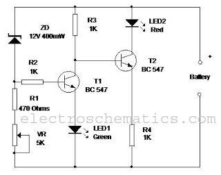
This circuit monitors the charging process of a 12 Volt Lead Acid or Tubular battery. The LED status indicates whether the battery is charging and signals when it reaches a full charge. It can be integrated into various battery...
The figure below illustrates a schematic of a highly sensitive microphone circuit designed to amplify faint sounds from a distance. The circuit exhibits significant sensitivity and offers substantial gain to weak audio signals. The microphone circuit typically consists of several...