
One synchronous motor thyristor excitation circuit
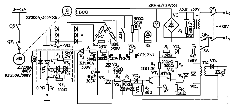
The synchronous motor circuit operates by utilizing alternating current (AC) to energize the field winding (BQ) while maintaining synchronization with the supply frequency. The AC excitation (G) is crucial as it generates the magnetic field required for the motor's operation. The interaction between the stator's rotating magnetic field and the rotor's magnetic field allows the motor to maintain a constant speed, which is determined by the frequency of the AC supply.
The de-excitation process, represented by the empty box in the circuit, is essential for controlling the motor's operation during various load conditions. When the motor is required to reduce speed or stop, the de-excitation mechanism reduces the current flowing through the field winding, allowing for a smoother transition and preventing sudden changes that could damage the motor or connected equipment.
In summary, the schematic provides a clear representation of the synchronous motor's operational principles, highlighting the importance of the field winding and AC excitation in maintaining consistent performance and the role of de-excitation in managing motor behavior under different operational scenarios. Circuit shown in Figure 16-105. Figure, MS synchronous motor. BQ its field winding; G AC excitation hair motors, BQG its field winding {empty box as part of the de-excitation.
Related Circuits
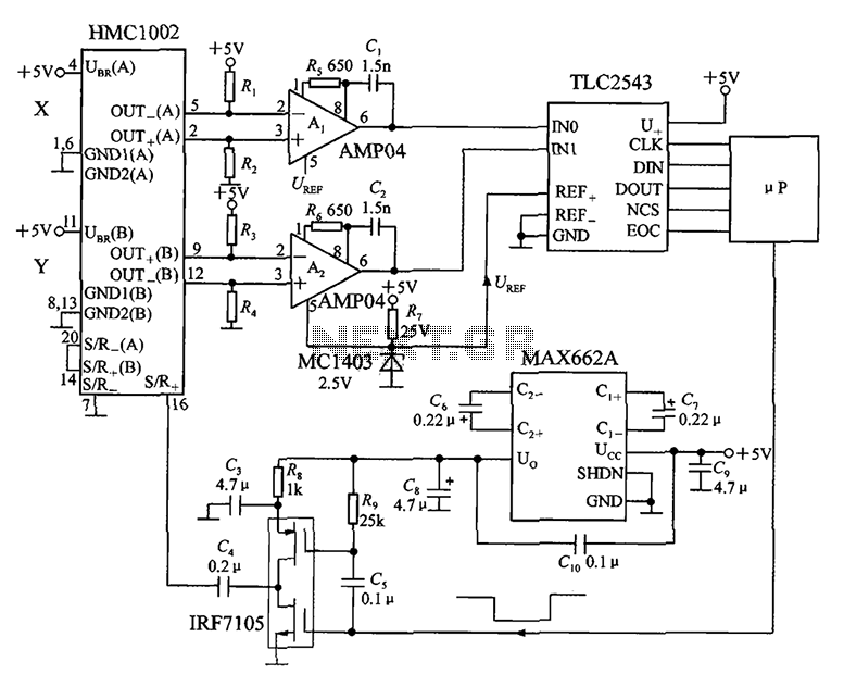
An application circuit for a biaxial magnetic field sensor is presented. This circuit utilizes the HMC1002 biaxial magnetic sensor along with two AMP04 amplifiers (A1, A2) to simultaneously measure magnetic fields in both the X-axis and Y-axis directions. The...
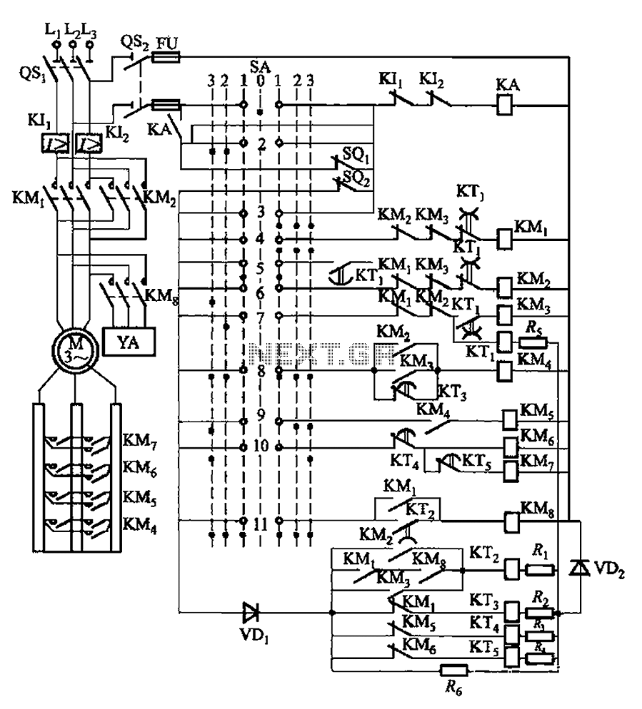
The system involves a master controller and a PQS1 Series Magnetic control panel, which includes a control circuit designed to manage the bridge crane hoist lifting mechanism. The master controller handle SA features seven positions: alongside the zero position,...
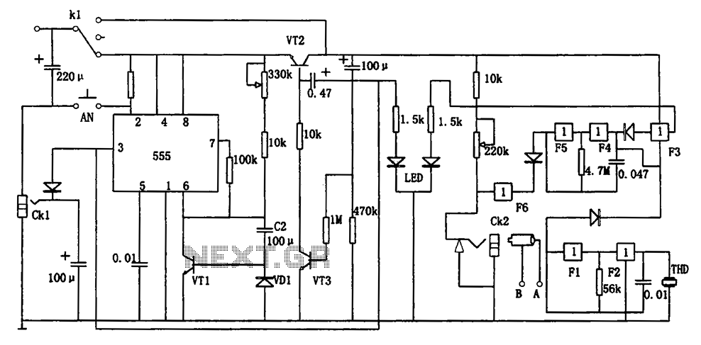
The circuit represents a general multi-function alarm and timing mechanism. Its timing capabilities range from 5 minutes to 3 hours. The timing components include C2, VD1, and VT1. The circuit utilizes a capacitance multiplier with a 555 timer. CK1,...

This 3V FM transmitter circuit is one of the simplest and most effective basic transmitters, offering a commendable transmitting range. It is remarkably powerful considering its small component count and 3V operating voltage. It can easily cover over three...

This second-order low-pass filter utilizes a 741 operational amplifier and can be tuned from 2.5 kHz to 25 kHz. The circuit is beneficial in audio and tone control applications. R1 and R2 are ganged potentiometers. The described circuit features a...
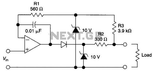
The circuit is designed to drive an external load. A fault condition in the external load circuit could feed excessive current or voltage back into the line drive circuit. If excessive voltage appears from the load, the two zener...
Warning: include(partials/cookie-banner.php): Failed to open stream: Permission denied in /var/www/html/nextgr/view-circuit.php on line 713
Warning: include(): Failed opening 'partials/cookie-banner.php' for inclusion (include_path='.:/usr/share/php') in /var/www/html/nextgr/view-circuit.php on line 713