
Battery Level Monitor Circuit
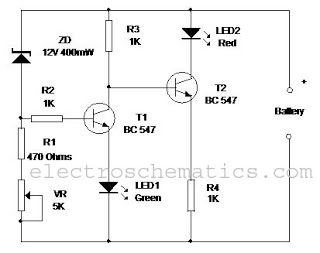
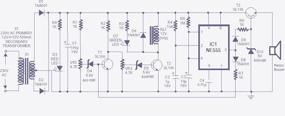
The circuit is designed to provide an effective visual indication of the charging status of a 12V Lead Acid or Tubular battery. It utilizes two NPN transistors (BC547) for switching, which enhances the reliability and responsiveness of the LED indicators. The Zener diode plays a crucial role in voltage regulation, ensuring that T1 is activated only when the battery voltage exceeds the specified threshold. This feature prevents false indications during low voltage conditions.
In practical implementation, the circuit can be adapted to different voltage levels by selecting appropriate Zener diodes. For instance, using a 6.1V Zener diode for a 6V charger or a 9.1V Zener for a 9V charger allows for versatility across various charging applications. The inclusion of a resistor (R1) and a variable resistor (VR) enables fine-tuning of the biasing conditions for T1, which is essential for optimizing the switching characteristics and ensuring that the LEDs operate smoothly without flickering.
The operational states of the LEDs provide clear and immediate feedback to the user. The green LED signifies that the battery is either in a normal operating range or fully charged, while the red LED indicates that the battery is currently charging. The design also incorporates a fail-safe feature, where the absence of the green LED illumination suggests that the battery is not accepting charge, prompting further investigation into the battery's health or the charger’s functionality.
Overall, this circuit is a practical solution for monitoring battery charging processes, providing essential feedback through simple LED indicators, and it can be easily adapted for various charging systems by modifying the Zener diode component.This simple circuit can monitor the charging process in 12 Volt Lead Acid battery or Tubular battery. The status of LED indicates whether the battery is accepting charge or not. It also indicates the full charge condition. The circuit can be incorporated in any battery charger like 6 volt, 9 volt, 12 volt etc. The only change needed is replacement of the Zener ZD with appropriate value. That is for 6 volt charger, use 6. 1 volt Zener and for 9 volt charger it should be 9. 1 volt Zener. The circuit is based on the switching of two NPN transistors (BC547) to drive the corresponding LED. Zener diode ZD is connected to the base of T1 so as to switch on T1 when the Zener conducts. This happens only when the battery voltage is above 12 volts. Green LED lights when the battery voltage is normal or battery attains full charge. Resistor R1 and Preset VR adjust the base bias of T1 for smooth switching. When T1 conducts, base of T2 will be pulled to ground and T2 turns off and Red LED extinguishes. 3. When the battery is connected to the charger, and if the battery is accepting charge, Green LED goes off and Red LED remains on. When the battery attains full charge, Green LED lights and Red LED goes off. 4. If the battery is not accepting charge, Green LED never lights, even after the prolonged charging. This indicates that the battery is not attaining the normal terminal voltage above 12 volts. 🔗 External reference
Related Circuits
This is an LM338-based power supply that is uncomplicated and easy to construct. It has been in use for an extended period without any issues. The circuit lacks a current adjustment feature, which has been addressed by incorporating an...
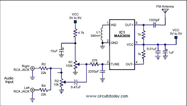
A simple single-chip FM transmitter circuit with a diagram and schematic using the IC MAX 2606, which is a high-performance voltage-controlled oscillator (VCO). The FM transmitter circuit utilizing the MAX 2606 is designed for efficient frequency modulation of audio signals....
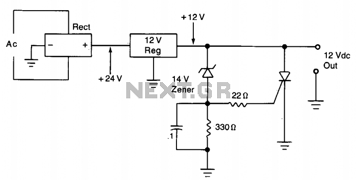
The silicon controlled rectifier (SCR) is designed to handle at least the current provided by the power supply. It is connected in parallel across the 12 V DC output lines but remains inactive until a voltage is applied to...
The high and low voltage cut-off with delay and alarm circuit, along with its circuit diagram, is explained in this post. The high and low voltage cut-off circuit is designed to protect electrical devices from damage caused by excessive voltage...
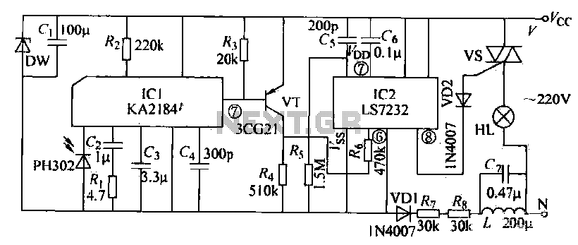
The receiving circuit operates as follows: when the infrared receiver detects a signal from the remote control transmitter, the KA2184 processes this signal, resulting in a low output at the pin. This low output is directly connected to the...

The thermostat electric circuit operates as depicted in the figure. It has three settings: off, low power (Lo), and high power (Peru HL). When the DIP switch SA is set to the Lo position, 220V AC is directed through...