
3 Band graphic equalizer circuit
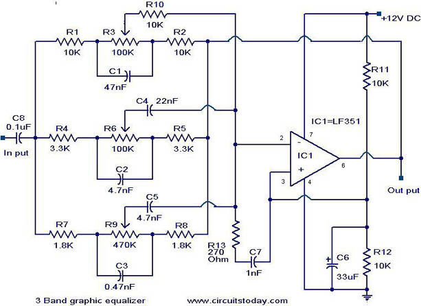
The three-band graphic equalizer circuit utilizes the LF351 op-amp, which is known for its low noise and high performance, making it suitable for audio applications. The circuit is designed to modify audio signals by selectively boosting or attenuating specific frequency ranges, enhancing the overall sound quality.
In this configuration, the op-amp is set up in an inverting amplifier arrangement, which allows for phase inversion and gain control. The gain of the circuit is determined by the feedback network formed by the resistors and the potentiometers. Each potentiometer (R3 for low frequencies, R6 for mid frequencies, and R9 for high frequencies) is connected to the inverting input of the op-amp, allowing the user to adjust the gain for each frequency band independently.
The input audio signal is fed into the circuit, where it first passes through a coupling capacitor to block any DC offset. The signal is then routed to the inverting input of the op-amp. The output of the op-amp is connected back to the inverting input through a feedback resistor, which, along with the potentiometers, sets the gain for each frequency band. The non-inverting input is typically grounded in this configuration.
The selected frequency ranges are achieved through the careful selection of resistor and capacitor values in conjunction with the potentiometers. The circuit can be fine-tuned to provide a flat frequency response or to emphasize certain frequencies, depending on the application requirements.
Overall, this simple yet effective equalizer circuit can be easily constructed and modified, making it an excellent choice for audio enthusiasts looking to enhance their sound systems with a customizable frequency response.Here is a simple 3 band graphic equalizer circuit made of a single op amp IC LF351 (IC1) and few passive components. The component values of this circuit are not very critical and can be replaced with nearest values with a little loss on the performance.
This feature make it easy to be assembled from your junk box. The opamp LF351 is wired to operat e in three frequency ranges- high, medium and low. The circuit is designed such that the circuit produces +/-20 dB boost or attenuation for 50Hz, 1KHz and 10Khz by varying POT`s R3, R6 and R9. The maximum amplification for any of these bands at maximum supply voltage is 20dB. The opamp LF 351 is wired as an inverting amplifier whose response to frequencies 50Hz, 1Khz and 10KHz can be varied by adjusting POT`s R3, R6 and R9.
🔗 External reference
Related Circuits
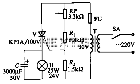
The circuit employs thyristor control. The flash frequency is determined by resistors Ri, RP, Rz, and capacitor C. By adjusting the electrical locator RP, the flash frequency can be varied from 0.5 Hz to several Hz. The described circuit utilizes...
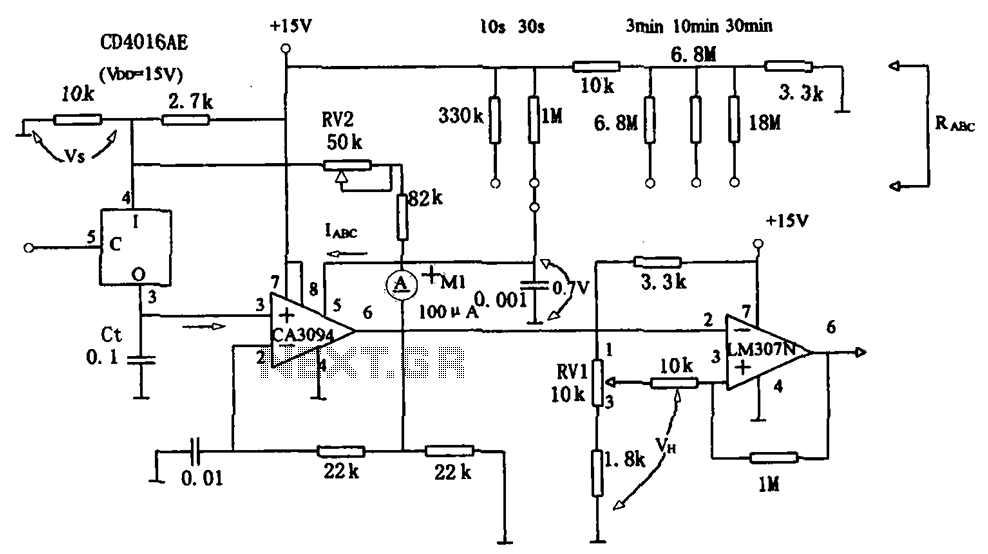
The long timer circuit utilizes an operational amplifier, specifically the CA3094, to control the discharge formula for extended timing. This is typically achieved by adjusting the variable resistor RV1, which alters the timing duration to meet specific requirements. The long...
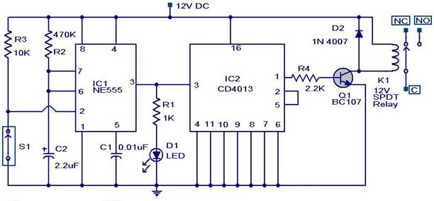
This weblog discusses electronic circuit schematics, PCB design, DIY kits, and electronic project diagrams. The circuit diagram presented is for a magnetic proximity switch, which has numerous applications across various fields. The circuit utilizes a magnetic reed switch (S1)...
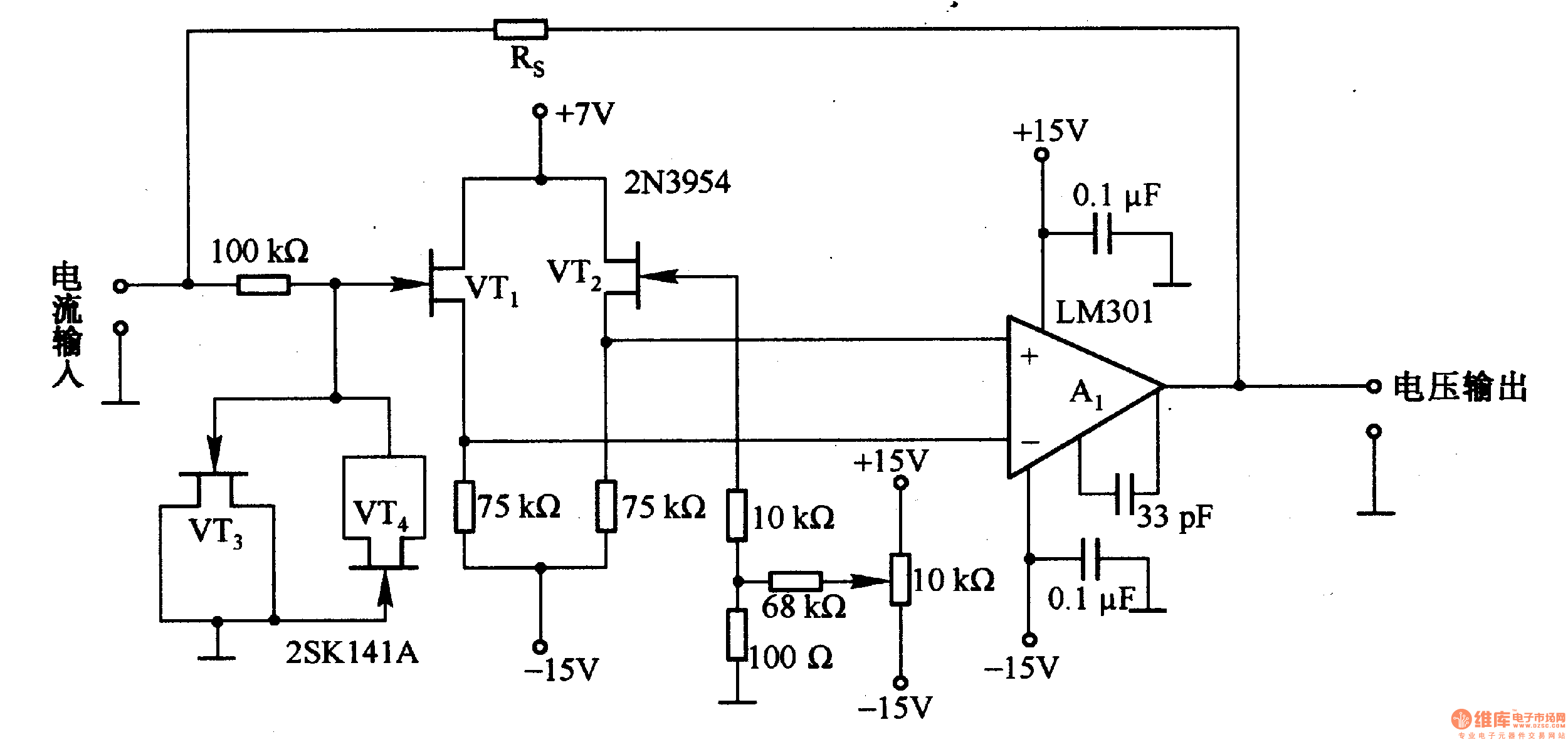
This is a low-input impedance conversion circuit with the reference resistor RS connected to the amplifier's feedback loop, resulting in an input impedance close to zero. The input current flows into the output end of the operational amplifier (Op-Amp)...
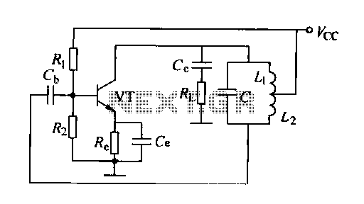
A feedback oscillator circuit utilizing inductance is presented, featuring the 3DG3 transistor. The component parameters reference values include: 1) transistors 3DG6, 2) resistances R1 at 91 kΩ, R2 at 11 kΩ, and R3 unspecified, 3) capacitance values of C...
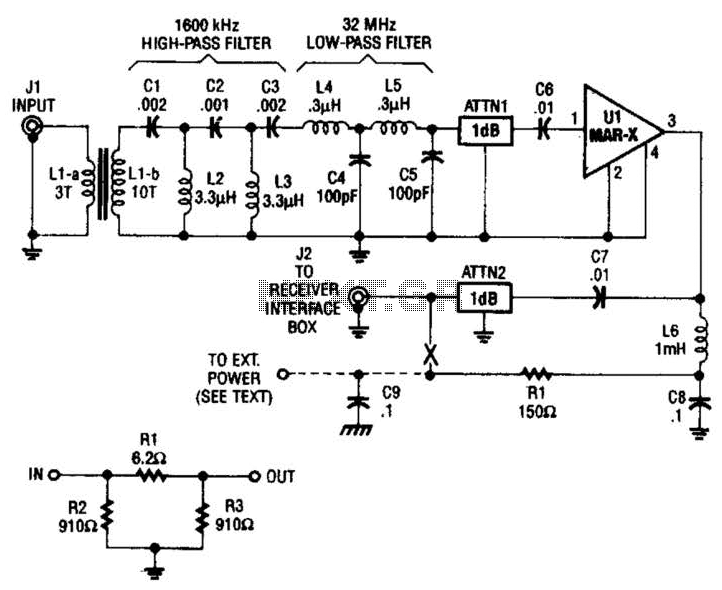
The HF/SW receiver preamplifier consists of a broadband toroidal transformer (LI-a and Ll-b), an LC network featuring a 1600-kHz high-pass filter and a 32-MHz low-pass filter, inductors L2 and L3 (26 turns of #26 enameled wire wound on an...