
Hf Broadband Antenna Preamp Circuit
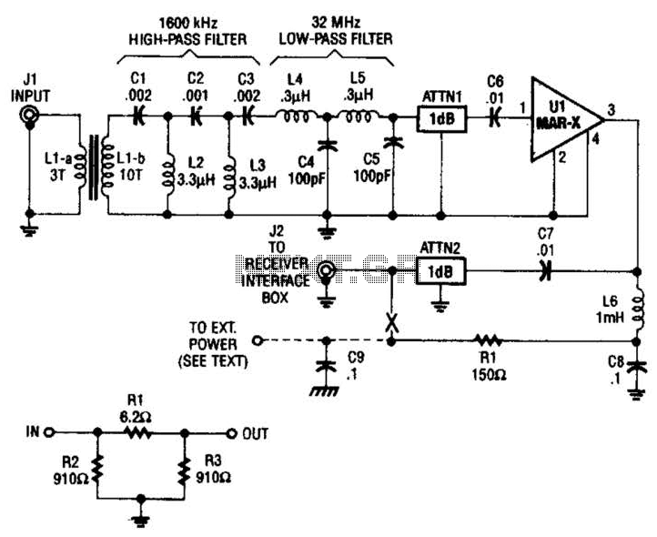
The HF/SW receiver preamplifier is designed to enhance the signal reception capabilities of high-frequency shortwave radio systems. The use of a broadband toroidal transformer allows for efficient impedance matching and broad frequency response, which is crucial for capturing a wide range of signals. The transformer components, LI-a and Ll-b, are integral in ensuring minimal signal loss and maintaining fidelity across the desired frequency spectrum.
The LC network plays a vital role in filtering out unwanted frequencies, with the high-pass filter set at 1600 kHz effectively blocking lower-frequency noise, while the low-pass filter at 32 MHz ensures that higher-frequency signals beyond this threshold are attenuated. This dual filtering mechanism helps to optimize the quality of the received signals, allowing for clearer audio output and improved overall performance of the receiver.
Inductors L2 and L3, constructed with 26 turns of #26 enameled wire on an Amidon Associates T-50-2 toroidal core, are configured to enhance the inductance and contribute to the stability of the circuit. The choice of a toroidal core minimizes electromagnetic interference and enhances the efficiency of the inductors.
The resistive attenuators, ATTN1 and ATTN2, are designed as a pi-network configuration, which effectively reduces the signal amplitude without introducing significant distortion. This is particularly useful in preventing overload of subsequent stages in the receiver, ensuring that the signal remains within optimal levels for processing.
The MAR-x device included in the design serves as a low-noise amplifier, which is crucial for boosting weak signals received by the antenna, thus improving the overall sensitivity of the receiver.
Furthermore, the method of supplying DC power through the RF coaxial cable is noteworthy as it simplifies the overall system design by eliminating the need for separate power lines. This approach allows for a cleaner installation and reduces the potential for interference from external power sources. This technique is particularly advantageous in portable or compact receiver designs where space and simplicity are paramount.
Overall, the combination of these components creates a robust preamplification stage that significantly enhances the performance of HF/SW receivers, enabling better reception of weak signals and improving the listening experience. The HF/SW receiver preamplifier is comprised of a broadband toroidal transformer (LI-a and Ll-b), LC network (comprised of a 1600-kHz, high- pass filter-and a 32-MHz, low-pass filter), L2 and L3 (26 turns of #26 enameled wire wound on an Amidon Associates T-50-2, red, toroidal core), a pair of resistive attenuators (ATTN1 and ATTN2), and a MAR-x device.Shown here is the composition of a basic 1-dB pi-network resistor antenuator. This is the method of supplying dc power to a preamplifier using only the RF coax cable. 🔗 External reference
Related Circuits
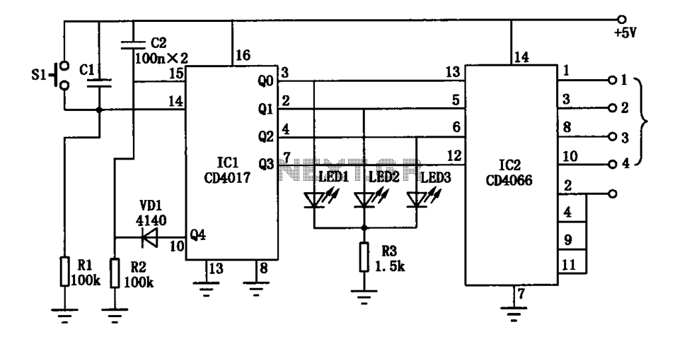
The electronic circuit diagram consists of the CD4017 and CD4066 components configured as a switch circuit. The CD4017 is a decade counter integrated circuit (IC) that can drive up to ten outputs, sequentially activating them based on clock pulses. It...
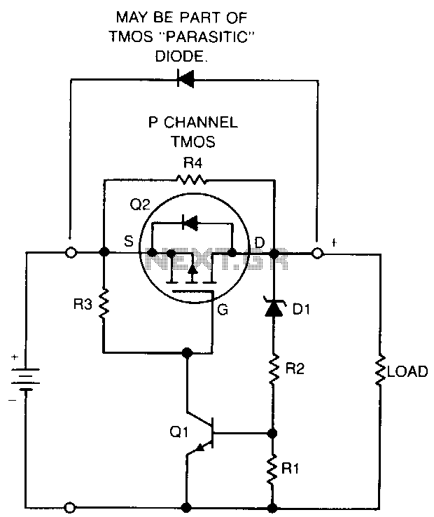
If a NiCad battery is discharged to the point where the lowest capacity cell becomes fully discharged and reverses polarity, that cell will typically short internally and become unusable. To prevent this type of damage, this circuit detects a...

This circuit turns off an amplifier or any other device when a low-level audio signal fed to its input is absent for at least 15 minutes. By pressing P1, the device is powered on, supplying power to any appliance...
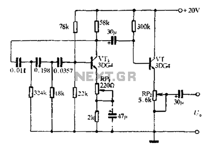
1 kHz RC phase shift oscillator circuit The 1 kHz RC phase shift oscillator circuit is designed to generate a continuous sine wave output at a frequency of 1 kHz. This circuit typically utilizes a combination of resistors and capacitors...
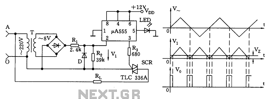
The zero volt switching circuit generates a trigger pulse at the zero crossing of the AC voltage. To facilitate this, the zero crossing of the 555 limit comparator is connected to a single form, with the comparison voltage set...
Ideal for operating 3 to 24V DC existing on-circuit lamps. This circuit was designed to provide continuous light for lamps already wired into a circuit. The circuit is intended to facilitate the operation of existing DC lamps that are integrated...
Warning: include(partials/cookie-banner.php): Failed to open stream: Permission denied in /var/www/html/nextgr/view-circuit.php on line 713
Warning: include(): Failed opening 'partials/cookie-banner.php' for inclusion (include_path='.:/usr/share/php') in /var/www/html/nextgr/view-circuit.php on line 713