
Four lights flash circuit

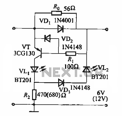
The described circuit utilizes a thyristor as the primary control element, which allows for efficient switching of the load by controlling the timing of the conduction phase. The flash frequency is influenced by the values of the resistors (Ri, RP, Rz) and the capacitor (C) in the timing circuit.
In this configuration, Ri sets a baseline resistance that influences the charging time of capacitor C. The capacitor's charge and discharge cycles establish the timing intervals, thereby determining the flash frequency. The resistor RP acts as an adjustable element; by varying its resistance, the time constant of the RC network can be modified, leading to changes in the frequency of the flashing output.
Rz may be included for additional stabilization or to set a minimum flash frequency, ensuring that the circuit operates within a specified range. The overall design allows for flexibility in operation, enabling the user to fine-tune the flash frequency to suit specific applications, such as in visual signaling or decorative lighting.
The thyristor's ability to handle high power makes this circuit suitable for applications where high current or voltage is required, while the RC timing network provides a straightforward method of frequency modulation. Proper attention must be given to the selection of components to ensure reliable operation and to achieve the desired frequency range.It uses thyristor control. Flash frequency is determined by Ri, RP, Rz and C. Adjusting the electrical locator RP, can change the flash frequency 0.5Hz to several Hz.
Related Circuits
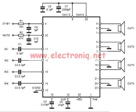
The input capacitor is used for low-frequency cut-off, with a standard value of 0.1 µF, resulting in a cut-off frequency of approximately 16 Hz. The input capacitor plays a crucial role in filtering unwanted low-frequency signals in electronic circuits. By...

If you plan to use this circuit with a 110V 60Hz supply instead of a 230V 50Hz supply, or if you intend to modify this circuit, please refer to the section titled "Common Questions about this Circuit" found below...
During the charging process, the green light-emitting diode (LED) VLi indicates that the battery is sufficiently charged, while the red light-emitting diode (LED) VLz illuminates when the battery is low. The circuit involves two light-emitting diodes (LEDs) serving as indicators...
Building circuits to interface an Amiga A1200 to a PC AT/ATX power supply and tower case. To create a reliable interface between an Amiga A1200 and a PC AT/ATX power supply and tower case, it is essential to design a...

This sound level measuring device circuit can be used to control the intensity of a sound recording in the field of a disco. It has five measurement ranges between 70 and 120 dB, with a measurement accuracy of 0.5...
The FM modulator circuit, which utilizes frequency modulation, is constructed using a Motorola MC1648P oscillator. Two varactors, specifically Motorola MV-209, are employed to modulate the frequency of the oscillator. A 5000-ohm potentiometer is incorporated to bias the varactors for...