
3 channel audio mixer

The audio mixer circuit based on the LM3900 IC is designed for versatility and ease of use, making it suitable for various audio applications. The inclusion of four Norton amplifiers allows for effective signal processing while minimizing the need for multiple power supplies. The circuit's current-controlled nature ensures that the output remains stable, even as input levels fluctuate.
The choice of resistor values is critical in determining the performance of the mixer. By selecting R2 and setting R4 to double this value, the designer can precisely control the gain of the amplifiers, facilitating optimal signal mixing. The adjustable input levels provided by potentiometers P1 and P3 enable users to tailor the audio signals to their desired levels, while the trimmer pots P4 to P6 allow for fine adjustments to accommodate different audio sources.
The summing of input signals through the fourth op-amp A4 is a key feature, as it combines the audio signals effectively, ensuring a coherent output. The resistors R3, R7, and R11 play a significant role in this summation process, allowing for balanced mixing of the three input channels.
The overall volume control through potentiometer P7 provides an easy means of adjusting the output level, catering to various listening environments. The ability to switch input channels on and off using switches S1 and S3 enhances the functionality of the mixer, enabling users to manage their audio sources dynamically. The option to replace mechanical switches with transistor gates further adds to the circuit's adaptability, providing a pathway for expansion and integration into more complex audio systems.
Overall, this audio mixer circuit offers a practical and efficient solution for mixing audio signals, making it a valuable tool for hobbyists and professionals alike.This audio mixer circuit uses an LM3900 IC but is not a profesional audio dj mixer. The IC houses four integrated Norton amplifiers. The advantage of using the four op amps is that they only need a single power supply. Since this amplifier circuit is current controlled, the DC bias is dependent on the feedback coupling. The schematic diagram shows inverting AC-Norton amplifiers. The DC output must be set at 50 percent of the power supply. In this case, a maximum output can be achieved without distortion (also called symmetrical limitation through overdrive). In designing this mini audio mixer circuit diagram you can freely choose the value of the resistor R2 (100k in the mixer schematic).
Set the AC voltage amplification factor through the ration of R2/R1. To set the amplifier gain correctly, choose the value of R4=2R2 (double the value of R2). Diagram 1. 0 shows the 3-channel sound mixer circuit using three Norton-opamps. The input levels can be set by potentiometers P1 or P3. Furthermore, each input level can be trimmed with the help of trimmers pots P4 to P6 to adapt each input to the source. The resistors at the non-inverting inputs of the opamps work as DC bias and set the DC output at 50 percent of the power supply for this powered audio mixer.
All three input signals are summed by the fourth opamp A4 through the resistors R3, R7 and R11. The commom volume level is cotrolled through the potentiometer P7. You can switch an input channel on or off through the switches S1 and S3. An input channel is turned off when its switch is closed. It is also possible to replace these mechanical switches with transistor gates. By doing so, you can build an analog multiplexer circuit that can be easily expanded by several inputs. 🔗 External reference
Related Circuits
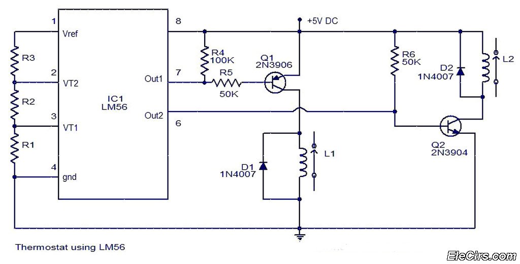
The LM56 Thermostat Project Circuit Diagram includes a schematic for the LM56 thermostat. The values of resistors R1, R2, and R3, which determine the required trip points VT1 and VT2, can be calculated using the following equations: VT1 =...
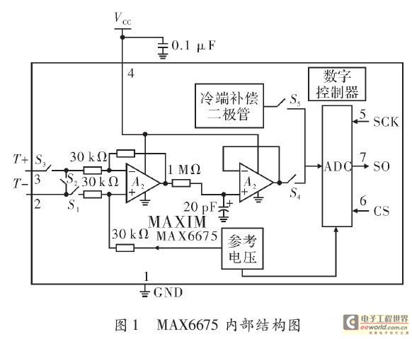
The K-type thermocouple is a commonly used temperature sensor in industrial production and scientific experiments. It can measure temperatures ranging from 0 to 1300 degrees Celsius in various applications, including direct measurements of gas, liquid, and solid surfaces. Its...
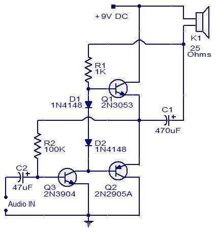
This circuit diagram illustrates a simple three-transistor audio amplifier capable of delivering approximately 100 mW of power to a 25 Ohm speaker. Diodes D1 and D2 provide a constant bias voltage for transistors Q1 and Q2. Transistor Q1 functions...
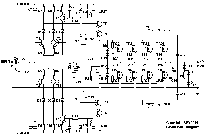
Here I propose a project of an AB class power amplifier, at its simplest, assembled with common components (not very expensive), based on traditional diagrams: a symmetrical differential input stage, a cascode stage driver, and a MOSFET output stage....
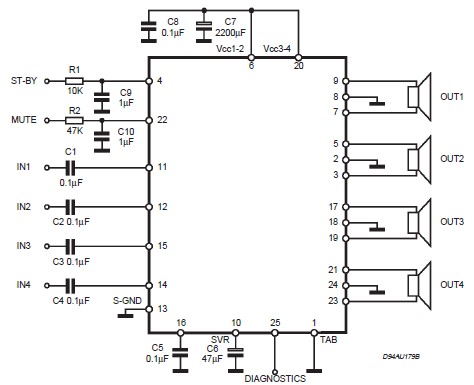
This circuit illustrates a car audio amplifier utilizing the TDA7381 integrated circuit (IC). The TDA7381 audio amplifier IC allows for the design of a straightforward 4x25 watts car radio. The TDA7381 is a high-performance audio amplifier designed specifically for automotive...
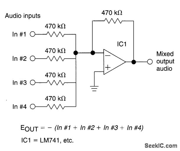
The circuit features four inputs. The voltage gain between each input and the output is maintained at unity by the relative values of the 470kΩ input resistor and the 470kΩ feedback resistor. The described circuit operates as a voltage buffer...