
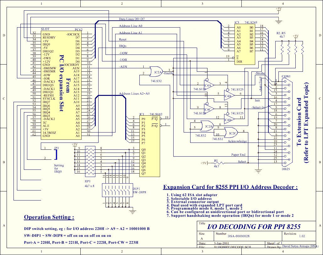
decoder circuit
The PPI-8255 Integrated Circuit (IC) is a versatile device designed for interfacing with microprocessors, enabling the control of various peripherals through programmable I/O ports. The PPI-8255 features three 8-bit ports (Port A, Port B, and Port C) that can be configured as either input or output, allowing for flexible communication with external devices. The ability to use the PPI-8255 for both expansion and direct I/O tasks enhances its functionality, making it an invaluable component in many electronic projects.
To implement the dual functionality of the PPI-8255, a robust I/O decoding mechanism is essential. The use of a 74LS682 comparator allows for effective address decoding, ensuring that the correct ports are accessed without ambiguity. The inclusion of a DIP switch provides a means to easily configure the address settings, thus accommodating various hardware configurations. Buffers are necessary to strengthen the signal integrity, especially when the expander card is located at a distance from the PC, preventing potential data loss or corruption.
During the initialization phase, it is critical that the expander card remains connected to the decoder card to ensure that the PPI is properly reset. This connection allows the internal state of the PPI to be configured correctly, enabling reliable operation. The addition of a push button switch to the reset pin provides flexibility, allowing users to connect the expander card without needing to reboot the system, thus streamlining the development process.
The programming model for the PPI-8255 is straightforward, with ports accessed through contiguous memory locations. This allows for efficient data transfer between the microprocessor and the PPI. The control word sent to Port CW dictates the operational mode of the ports, enabling users to configure the PPI for specific tasks such as input reading or output driving.
Overall, the PPI-8255 serves as a powerful interface for I/O operations, with the ability to adapt to various hardware configurations and programming requirements, making it an essential tool for electronics engineers and hobbyists alike.As you can see from the article LPT port expander, this PPI-8255 is a general purpose I/O programmable function. But usually this IC are tired to the computer bus directly. Return to this idea, here I will show you that the card can be used to dual function purpose. Beside for the expander port, it can be used for I/O functional directly. So we c an used the card both for the expander experiment or for direct connection to the computer bus experiment. Why do you need this I/O directly connection for Many article on the net usually used this method for I/O interfacing.
So by doing this, we can take 2 benefits. First, we can used many useful routines (usually with the tested ones) or directly used the softwares ( ) or routines; secondly, we can used many hardware design by someone else (compatibility type). At most we can replace the I/O parts. Happy programming and happy surfing on the net. To directly connected a hardware to computer bus, we need an I/O decoding. Here I don`t explain anymore, please refer to the topic of decoding technique at the other page. There are 2 type of decoding technique, ie: partial decoding, when we want to reduce the components using or full decoding.
I prefer the last one. The decoder circuit must be preserve all of the possible unused I/O ports, easy to select the address, and not ambiguous for the future compatibility design. I used a comparator 74LS682 type and a dip switch for this purpose. Besides that the lines need buffers because the card may put far away from the PC. The complete circuit diagram shown at fig-1. One thing must remember that, when doing re-boot-ing the PC, the expander card must be connected to this decoder card.
So the PPI can be reset. If not, the PPI can not be initialized. To anticipate this purpose, we can add a push on switch between +Vcc and reset pin of PPI. So you can connected the expander card at any time, when ever you want and without re-boot-ing the PC. Initialized perform when the software being execute. Some connection also must be changed to make the circuit work with this decoder card. The explanation will be clearly later. Nothing to say about this card programming. It is quiet easy. You can access the port by accessing directly to 4 contiguous port location, eg: if the decoder set to port 220 hex, so port-A = 220 H, port-B = 221 H, port-C = 222 H, port-CW = 223 H.
First, initialize it by sending the control word data to port-CW (control word data contain mode setting for each port). Refer to PPI-8255 data book for more detailed explanation. Then each port can be accessing directly. Here are a sample of initialize routine for mode-0 for any language. CONST Base_Port = $220; Port_A = Base_Port; Port_B = Base_Port+1; Port_C = Base_Port+2; Port_CW = Base_Port+3; CW_Data = $82; { Port-A = output, Port-B = input, port-C = output } PROCEDURE Initialize_Port; BEGIN PORT[Port_CW] := CW_Data; { Send Control Word } END; PROCEDURE Read_Write_Port_A(Datanya : BYTE); BEGIN.
PORT[Port_A] := Datanya; { Send a Byte }. END; FUNCTION Read_Port_B : BYTE; BEGIN. Read_Port_B := PORT[Port_B]; { Receive a Byte }. END; Base_Port EQU 220 H Port_A EQU Base_Port Port_B EQU Base_Port+1 Port_C EQU Base_Port+2 Port_CW EQU Base_Port+3 CW_Data EQU 82 H ;Port-A = output, Port-B = input, Port-C = output Dummy EQU 5A H Initialize_Port PROC NEAR MOV DX, Port_CW MOV AL, CW_Data ;Send Control Word OUT DX, AL RET Initialize_Port ENDP Write_Port_A PROC NEAR. MOV DX, Port_A MOV AL, Dummy ;Send a Byte OUT DX, AL. RET Write_Port_A ENDP Read_Port_B PROC NEAR. MOV DX, Port_B IN AL, DX MOV Dummy, AL ;Receive a Byte. RET Read_Port_B ENDP Write_Port_C PROC NEAR. MOV DX, Port_C MOV AL, Dummy ;Send a Byte OUT DX, AL. RET Write_Port_C ENDP Base_Port = &H220 Port_A = Base_Port Port_B = Base_Port+1 Port_C = Base_Port+2 Port_CW = Base_Port+3 CW_Data = &H82 ;REM - Port-A = output, Port-B = input, Port-C = output Dummy = &H5A #define Base_Port 0x22
🔗 External reference
Related Circuits
The circuit depicted in Figure 3-131 utilizes a relay instead of a speed control relay. It is designed to operate effectively in dusty environments and other challenging conditions. The circuit operates by employing a relay as a primary switching mechanism,...

A compact audio amplifier circuit utilizing the TDA 7052 integrated circuit from Philips. This circuit is suitable for use as a pocket radio amplifier, delivering an output power of 2 watts. The TDA 7052 is a low-voltage audio amplifier designed...
The first BC109C transistor functions as a buffer, delivering a high input impedance of approximately 250k and exhibiting a voltage gain marginally below unity. Given that the Baxendall tone control circuit operates passively, it attenuates all audio frequencies. The...
The following circuit illustrates a Tachometer Circuit Project. This circuit is constructed using the 555 Timer IC. Features include a monostable IC and voltage capabilities. The Tachometer Circuit utilizes a 555 Timer configured in monostable mode to measure the rotational...
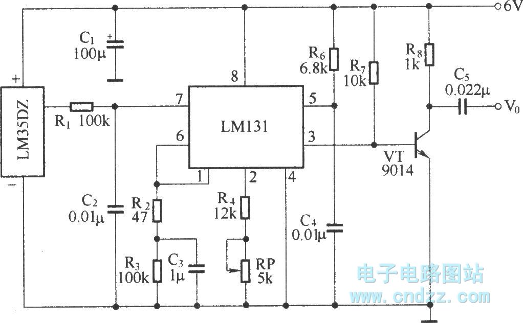
The circuit depicted in the figure integrates a temperature detection system, a temperature-voltage switch, and a voltage-frequency switch to enable remote temperature monitoring. This circuit is connected to a wireless transmission circuit, creating a remote control temperature detection system....
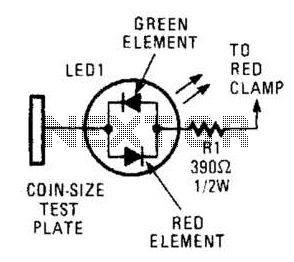
This circuit comprises a tri-color LED, a resistor, wire, and a coin-sized test plate. Two circuits must be constructed, one for each black clamp on a set of auto battery jumper cables. The circuits are installed inside the black...