
3 Line Mixers
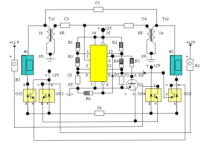
The mixer circuit is designed to combine multiple audio signals into a single output. Each input line is typically connected to a potentiometer (P) set to 10K ohms, which serves as a volume control for that specific input. The resistors (R) used in the circuit are 22K ohms, which help to manage the overall impedance and ensure signal integrity across the mixer.
To accommodate more than three input signals, the input sections can be replicated as needed. Each additional input section will consist of its own potentiometer and resistor, allowing for independent volume control of each input. This modular approach enables flexibility in the design, making it suitable for various applications, such as small audio mixing setups or for use in synthesizers.
The power supply for the mixer is a 9V DC source, which is standard for many audio circuits. This voltage level provides sufficient headroom to avoid distortion while maintaining low noise levels. Proper decoupling capacitors should be included in the power supply line to filter out any noise that could affect the audio quality.
The output of the mixer can be connected to an amplifier or directly to speakers, depending on the application. It is essential to ensure that the output stage is capable of handling the combined signals from all input lines without distortion. Additionally, careful attention must be paid to grounding and shielding to prevent interference from external sources.
Overall, this mixer design is a versatile solution for combining multiple audio signals, with the ability to customize the number of inputs and maintain control over each channel's volume.This project is a 3 or more lines mixer. For more than 3 inputs you can repeat the input parts (P=10K R=22K). It powered with 9Vdc.. 🔗 External reference
Related Circuits
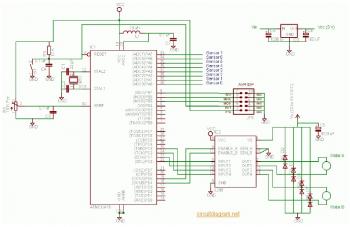
The complete electrical circuit diagram of a line follower robot is based on the ATmega16 microcontroller. This robot consists of three primary modules: the sensor module, the microcontroller module, and the DC motor module. A comprehensive tutorial, including circuit...
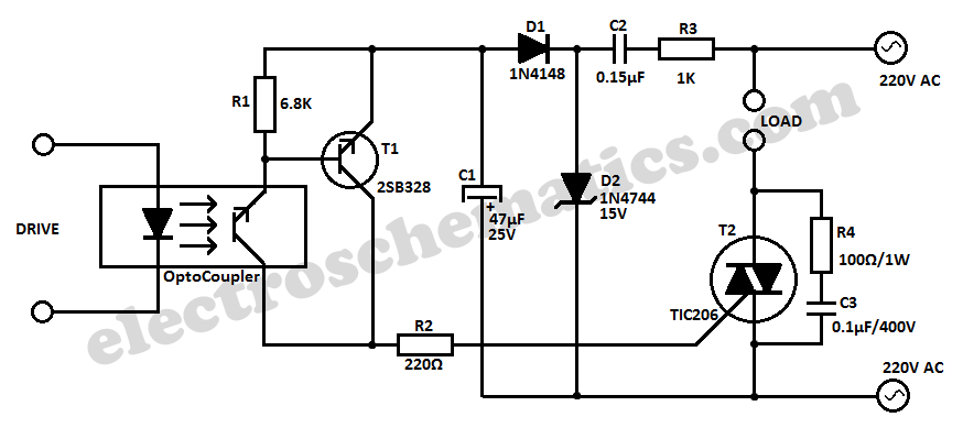
This simple 220V power interface is designed for monitoring electrical equipment and devices using a computer. The interface only detects whether the monitored device is powered on or off. A key feature of this circuit is the galvanic isolation...
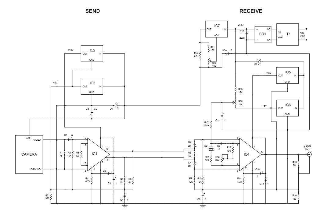
The Videowire converts a baseband video signal into a low impedance differential signal that can be sent over ordinary four conductor telephone wire. A send board mounted close to the camera generates the differential signal and a receive board...
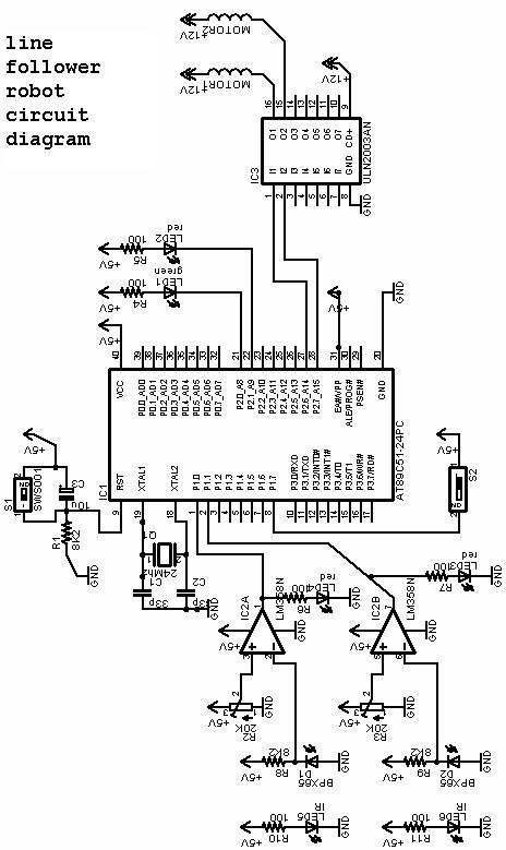
The project involves a line follower robot utilizing the 8051 microcontroller, accompanied by a circuit diagram. A full project report on the line follower or chaser robot is available for download. The line follower robot is designed to autonomously navigate...
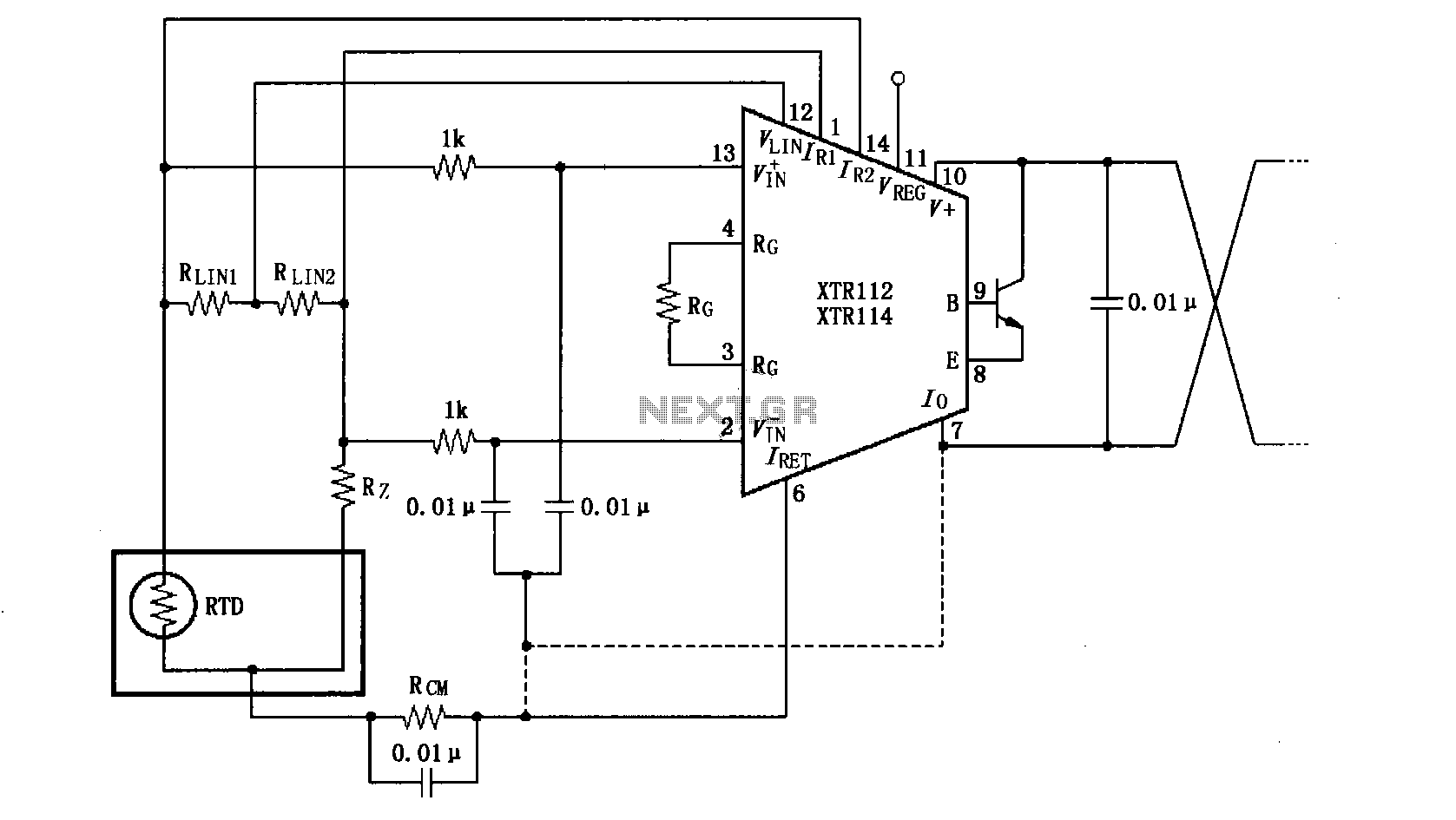
The length of the transmission wire in a current loop circuit can introduce radio frequency (RF) interference. This RF energy may lead to input errors in sensitive devices such as the XT112/114, causing instability in loop current or input...
The phone company provides 3 levels of power. With no devices 'off hook' the line rests at 48 volts DC. If you draw any more than a fraction of a milliamp or so, you get the phone company's attention...