
A Joule Thief Circuit
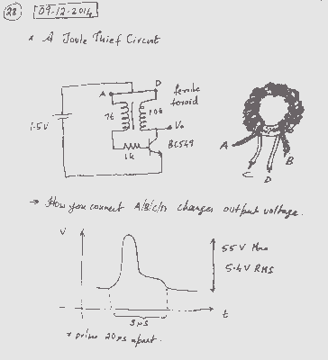
The Joule Thief is a minimalist boost converter designed to extract energy from low-voltage sources, such as depleted batteries, and increase the voltage to a usable level. This circuit is particularly useful for powering low-current devices from single-cell batteries, enabling the utilization of nearly all the energy stored within the battery.
The core components of a Joule Thief circuit typically include a transistor, a resistor, a toroidal ferrite core, and a small inductor or winding. The circuit operates on the principle of oscillation, where the transistor switches on and off rapidly, creating a magnetic field in the inductor. When the transistor is turned off, the collapsing magnetic field induces a voltage spike, which can be significantly higher than the original supply voltage.
To construct the Joule Thief, the following steps outline the necessary components and connections:
1. **Transistor**: A small-signal NPN transistor, such as the 2N3904 or BC547, is used as the main switching element. The transistor's collector is connected to one end of the inductor.
2. **Inductor**: A toroidal ferrite core is wound with a few turns of insulated copper wire to form the inductor. Typically, around 10 turns can be sufficient. One end of the inductor connects to the collector of the transistor, while the other end connects to the positive terminal of the power source.
3. **Resistor**: A resistor (commonly between 1kΩ and 10kΩ) is connected from the base of the transistor to the positive terminal of the power source. This resistor helps to bias the transistor, allowing it to switch on.
4. **Feedback Loop**: A feedback winding is created by adding a few turns of wire around the same core, connecting this feedback winding to the base of the transistor. This feedback is crucial for sustaining oscillation.
5. **Power Source**: The circuit can be powered by a single AA or AAA battery. The negative terminal of the battery connects to the emitter of the transistor.
6. **Output Load**: The output voltage can be taken from the collector of the transistor. The circuit can drive low-power LEDs or other devices that operate at higher voltages than the source.
The Joule Thief circuit is efficient and can extend the life of batteries by utilizing energy that would otherwise be wasted. This simple design demonstrates the principles of energy conversion and oscillation in electronics, making it an excellent project for both educational purposes and practical applications.I was looking for a simple voltage boost circuit when I found that Joule Thief. Now lets look at building the circuit. 🔗 External reference
Related Circuits
This technique eliminates the need for an additional cable to power the FM antenna amplifier. The RF signal and the DC current that supplies the amplifier utilize the same cable simultaneously. An FM antenna booster circuit diagram can be...
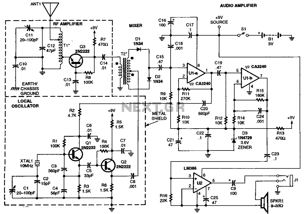
The RF amplifier Q3 connects to diodes D1 to D4 within the mixer. Transistors Q1 and Q2, through transformers T1 and T2, facilitate the injection of liquid oxygen at 10 MHz for diodes D1, operational amplifier U1A, and U1B....
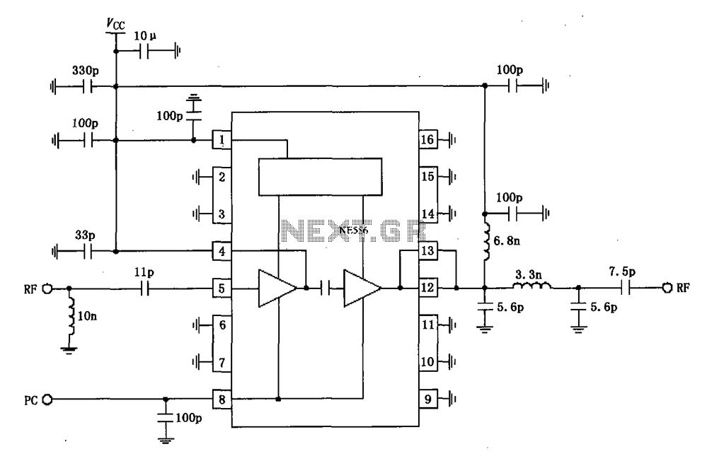
The RF2104 830MHz amplifier circuit operates as illustrated in the figure. A radio frequency (RF) signal enters through a 5-foot input, passes through a preamplifier, and is then amplified by an amplifier stage at the 12-pin output. The circuit...
Running Message Display Circuit Diagram. This circuit is based on the CD401 IC. Features: Light emitting diodes are advantageous due to their smaller size. The Running Message Display Circuit utilizes the CD401 integrated circuit, which is a versatile component in...

This is an application circuit for calibration known as a high voltage AC calibrator circuit. An essential aspect of sine wave oscillator design is the stable control of amplitude. This circuit not only stabilizes the amplitude through servo control...
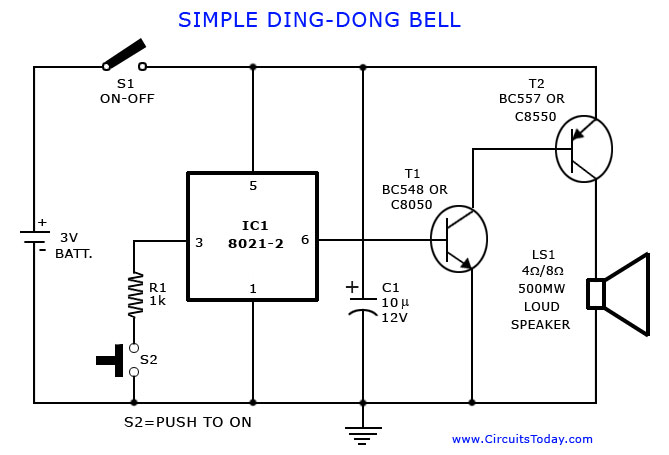
A tone generator circuit, which can be used to create a simple calling bell circuit, is illustrated here. It is constructed using the 8021 integrated circuit (IC), which includes built-in circuitry for producing a "ding-dong" sound. The tone generator circuit...