
Medium power FM Transmitter Circuit With BC547 Transistor

The described FM transmitter circuit utilizes two transistors to facilitate the modulation and amplification of audio signals. The circuit begins with a microphone that captures voice signals, which are then fed into the first transistor configured as a common emitter amplifier. This configuration provides initial amplification of the audio signal, ensuring that it is strong enough for further processing.
The amplified audio signal is then fed into the second transistor, which serves as an oscillator. This transistor is configured to modulate the audio signal onto a carrier frequency, typically within the FM band. The modulation process involves varying the frequency of the carrier wave in accordance with the amplitude of the audio signal, resulting in an FM signal that can be transmitted over the air.
The circuit may include additional components such as resistors and capacitors to stabilize the operation of the transistors and to filter the output signal. An LC tank circuit may also be incorporated to determine the transmission frequency and enhance the quality of the emitted signal. The output of the second transistor is then connected to an antenna, which radiates the modulated signal, allowing it to be received by FM radios within range.
Overall, this moderate power FM transmitter circuit offers a straightforward design for transmitting audio signals wirelessly, making it suitable for various applications, including personal broadcasting and educational demonstrations. Proper attention to component selection and circuit layout is essential for achieving optimal performance and signal clarity.The moderate power FM transmitter circuit employing two transistors.The voice signals picked by the microphone will be amplified by the transistor .. 🔗 External reference
Related Circuits

Tape isolate single-phase power factor correction (PFC) that utilizes DC/DC converters, consisting of two cables. The three-phase PFC is formed by connecting three single-phase PFCs in parallel at the output. This configuration is based on a matrix-type DC/DC converter...
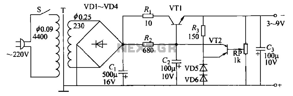
A 3-9V adjustable 100mA power supply is presented, featuring a series regulator circuit that utilizes amplifier tubes. The output voltage can be continuously adjusted between 3V and 9V, with a maximum output current of 100mA, making it suitable for...
The circuit for the power amplifier has a power output of up to 1500W RMS and is commonly utilized in outdoor sound systems. The final image displays a series of power amplifiers that utilize 10 sets of power transistors....
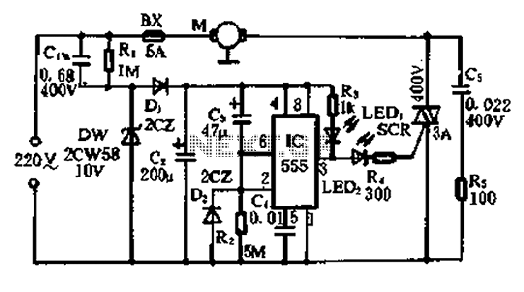
A 5-minute circuit can continue to operate during a power outage, providing protection for the refrigerator. The refrigerator power protection circuit, designated as 1136, includes a power transformer that converts 220V voltage through a rectifier bridge (VD1). This setup...
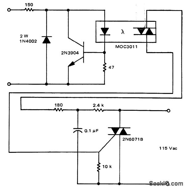
A solid-state relay circuit features an input protection mechanism utilizing the MOC3011 triac driver. The input voltage for the protection circuit can range from 3 to 30 volts DC, as noted by Motorola Semiconductor Products Inc. The solid-state relay (SSR)...
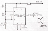
This circuit generates an oscillating frequency of approximately 1 kHz, which can be adjusted by changing the value of resistor R1. The speaker will emit a continuous beep sound at this frequency. The circuit utilizes a basic oscillator configuration,...