
300w rf power amplifier circuit
The 300 W RF amplifier is an essential component for FM broadcasting applications, providing the necessary power to transmit signals over a wide area. The design incorporates two TP9383 transistors, which are known for their high efficiency and reliability in RF applications. These transistors are configured to work in a push-pull arrangement, allowing for improved linearity and reduced distortion in the transmitted signal.
The amplifier's input stage is typically designed to accept signals from a low-power source, such as an audio mixer or a preamplifier. The signal is then fed into the TP9383 transistors, where it is amplified to the desired output power level. Proper biasing of the transistors is crucial to ensure optimal performance, and this is usually achieved through a combination of resistors and capacitors that stabilize the operating point.
The output stage of the amplifier includes a matching network that adapts the impedance of the amplifier to that of the antenna system, ensuring maximum power transfer and minimizing signal reflections. This matching network may consist of inductors and capacitors arranged to create a bandpass filter that enhances the desired frequency range while attenuating unwanted harmonics.
Thermal management is another critical aspect of the amplifier design. Adequate heat sinking and possibly active cooling solutions are implemented to dissipate the heat generated by the transistors during operation, thereby ensuring longevity and reliability of the amplifier.
Overall, this 300 W RF amplifier is a robust solution for FM transmission, providing high output power and excellent performance characteristics for broadcasting applications within the specified frequency range.Here you got it! 300 W rf authentic ability for fm transmission. 300 W radio ability amplifier for accomplished 88 108 MHz ! This fm amplifier has 2 TP9383 abundant to bear up to 300W. 🔗 External reference
Related Circuits
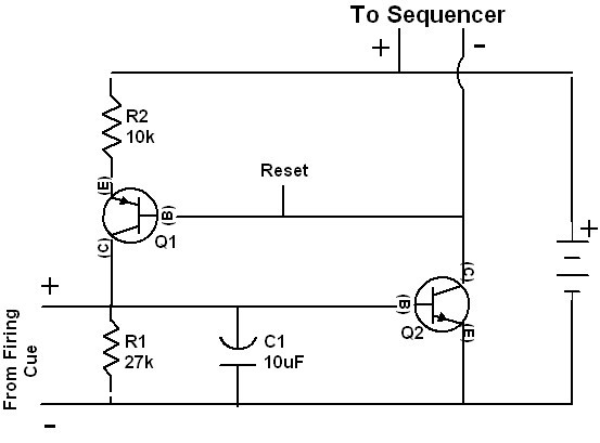
The 4017 integrated circuits are not initialized to a known state because the reset pins are not briefly forced high when the circuit is powered on. While the chips might typically power up in the normal reset condition, this...
A switch-mode power supply provides ±15V or ±12V at 0.5A output from a 4.5V to 12V input. The wide input voltage range allows flexibility to be powered from a regulated DC voltage. The switch-mode power supply (SMPS) described operates within...
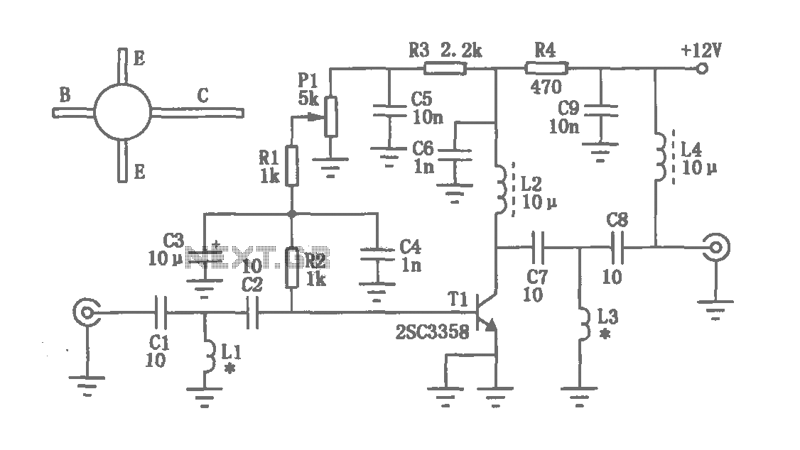
The circuit depicted in the figure operates within a frequency range of 400 to 850 MHz, designed as a UHF amplifying circuit. For optimal performance and results, it is recommended that the circuit be manufactured using silver-tin processing techniques. The...
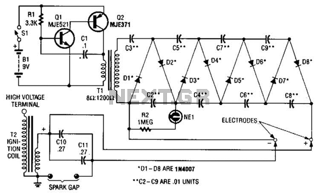
This circuit employs a transistor oscillator and a voltage multiplier to charge capacitors CIO and CI1 to a high voltage. When the spark gap breaks down, T2 generates a high-voltage pulse through the discharge of capacitors CIO and CI1...
Stereo tube amplifier circuit built with 5 power tubes: 6SQ7-GT, 6V6-GT, and 5Y3-GT. This circuit generates up to 4 watts of audio output per channel. The stereo tube amplifier circuit utilizes a combination of five power tubes, specifically the 6SQ7-GT,...
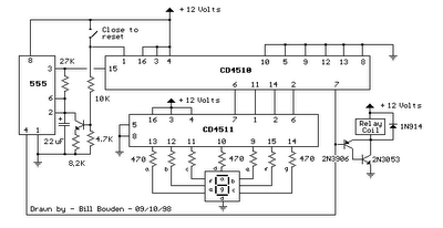
When the switch is opened, the timer generates an approximate 1-second clock signal, decrementing the counter until it reaches a count of zero. Upon reaching zero, the carry-out signal at pin 7 of the counter goes low, energizing a...
Warning: include(partials/cookie-banner.php): Failed to open stream: Permission denied in /var/www/html/nextgr/view-circuit.php on line 713
Warning: include(): Failed opening 'partials/cookie-banner.php' for inclusion (include_path='.:/usr/share/php') in /var/www/html/nextgr/view-circuit.php on line 713