
3170 IC For Telephone Remote Control Circuit
The teleremote circuit operates by utilizing telephone lines to control electrical appliances remotely. The primary components of this circuit typically include a telephone line interface, a microcontroller or relay module, and the connected appliances.
When a user makes a call to the designated telephone number associated with the teleremote system, the circuit detects the incoming call. The microcontroller processes the call signals and interprets the commands based on the duration of the ring or specific tones sent by the caller. For instance, a short ring may signify a command to turn an appliance on, while a longer ring could indicate a command to turn it off.
The circuit may also incorporate a relay or solid-state switch to handle the high current required by electrical appliances. This ensures safe operation, as the microcontroller typically operates at low voltage levels. The relay acts as an intermediary, allowing the low-power control signal from the microcontroller to switch the higher power required by the appliance.
Additionally, the teleremote circuit can be enhanced with features such as feedback indicators, which inform the user of the current state of the appliance (on or off) through LED indicators or through a voice response system. This feedback can be crucial for users to confirm that their commands have been executed successfully.
Overall, this teleremote circuit design provides a convenient solution for remotely managing household appliances, leveraging existing telephone infrastructure for control and communication.This circuit bellow shows a teleremote circuit which enables switching ?on? and ?off? of appliances through telephone lines. Can be used . 🔗 External reference
Related Circuits
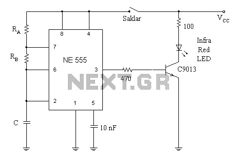
A simple circuit diagram illustrates a schematic for a remote control system, which consists of two components: a transmitter and a receiver. The transmitter circuit is controlled by the NE555 integrated circuit (IC). This system operates by detecting the...
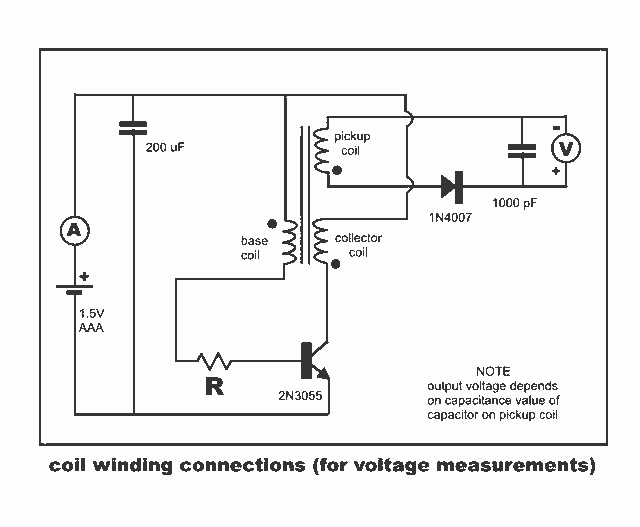
New Jewel Thief "Resonate LCR Circuit" with significantly reduced energy consumption. Measurements of voltage and current for the Joule thief. The Jewel Thief circuit, particularly the "Resonate LCR Circuit," is an innovative low-power design that enhances energy efficiency while maintaining...
The OPB350 series liquid sensor is designed to operate with clear tubes of various outer diameters: 1/16 inch (1.6 mm), 1/8 inch (3.2 mm), 3/16 inch (4.8 mm), and 1/4 inch (6.3 mm). When integrated with output reference circuitry,...
This LED flasher circuit is a classic two-transistor flip-flop. It is a popular circuit often built by beginners in the electronics hobby. The schematic diagram of this well-known LED flasher circuit includes two transistors, two capacitors, four resistors, and...
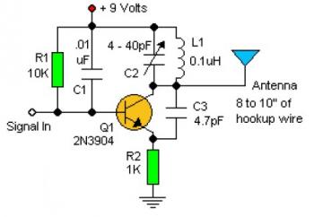
Experimenting with the size of the coil and the number of turns can influence the frequency and signal output of the oscillator. The signal can be received using a standard FM radio receiver. The input signal should be coupled...
Each time switch S1 is closed the count on the CD4017 advances by 1 step and the corresponding LED turns on. When the maximum count plus 1 is reached for each circuit the cycle is restarted and repeats. The circuit...
Warning: include(partials/cookie-banner.php): Failed to open stream: Permission denied in /var/www/html/nextgr/view-circuit.php on line 713
Warning: include(): Failed opening 'partials/cookie-banner.php' for inclusion (include_path='.:/usr/share/php') in /var/www/html/nextgr/view-circuit.php on line 713