
Basic RF Oscillator circuit diagram

The oscillator circuit described involves fundamental principles of inductance and capacitance, which directly affect the frequency of oscillation. The size of the coil, determined by its diameter and the number of turns, plays a critical role in defining the inductance value, which, in conjunction with the capacitive element, sets the resonant frequency of the oscillator. The resonant frequency (f) can be calculated using the formula:
\[ f = \frac{1}{2\pi\sqrt{LC}} \]
where L is the inductance in henries and C is the capacitance in farads. By adjusting the coil size and the number of turns, one can fine-tune the inductance, thus affecting the overall frequency output of the oscillator.
The coupling of the oscillator's output signal to the next stage is achieved through a disc capacitor of approximately 0.1 µF. This capacitor serves as a high-pass filter, allowing the AC signal generated by the oscillator to pass while blocking any DC components. This is crucial for ensuring that only the desired frequency components are transmitted to the subsequent circuit stage, which could be an amplifier or a modulator.
To receive the oscillator's signal, a standard FM radio receiver can be utilized. The radio receiver is designed to pick up frequency-modulated signals within a specific frequency range. By tuning the receiver to the oscillator's output frequency, the signal can be demodulated and processed, allowing for the transmission of information encoded onto the carrier wave.
In practical applications, the oscillator can be integrated into various communication systems where information needs to be transmitted over radio frequencies. The ability to modify the coil and capacitor values allows for versatile designs tailored to specific communication requirements. It is essential to ensure that the components used are rated appropriately for the desired frequency and power levels to maintain signal integrity and prevent component failure.You can experiment with the size of the coul and the number of turns to see how it affects the frequency and signal output of the oscillator. You should be able to pick up its signal with standar FM radio receiver. The Signal In should be coupled by disc capacitor of about 0. 1uF to the stage in front of it. We aim to transmit more information b y carrying articles. Please send us an E-mail to wanghuali@hqew. net within 15 days if we are involved in the problems of article content, copyright or other problems. We will delete it soon. 🔗 External reference
Related Circuits
This circuit allows the use of an inexpensive loudspeaker as a microphone. Sound waves that reach the speaker cone cause fluctuations in the voice coil. The movement of the voice coil within the speaker's magnetic field generates a small...
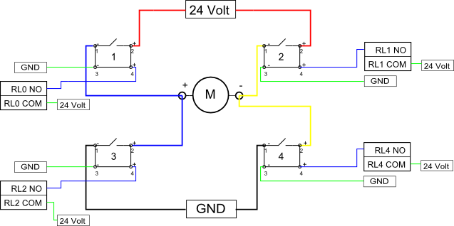
Eight solid-state relays (SSR) and an ADAM-4068 (Serial-I/O device) are utilized to wire a circuit for controlling a motor in a robotic application. The ADAM-6048 is a versatile device that facilitates control of digital inputs and outputs via RS-485...
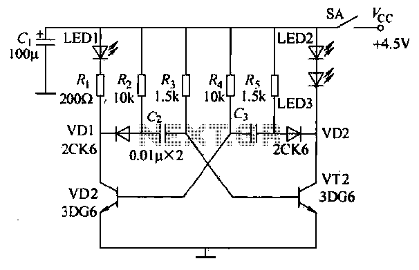
The infrared transmitter circuit, as depicted in Figure 18-la, utilizes transistors VT1 and VT2 along with RC components to create an astable multivibrator. The circuit operates with VT1 and VT2 receiving base bias from resistors, and closing switch SA...
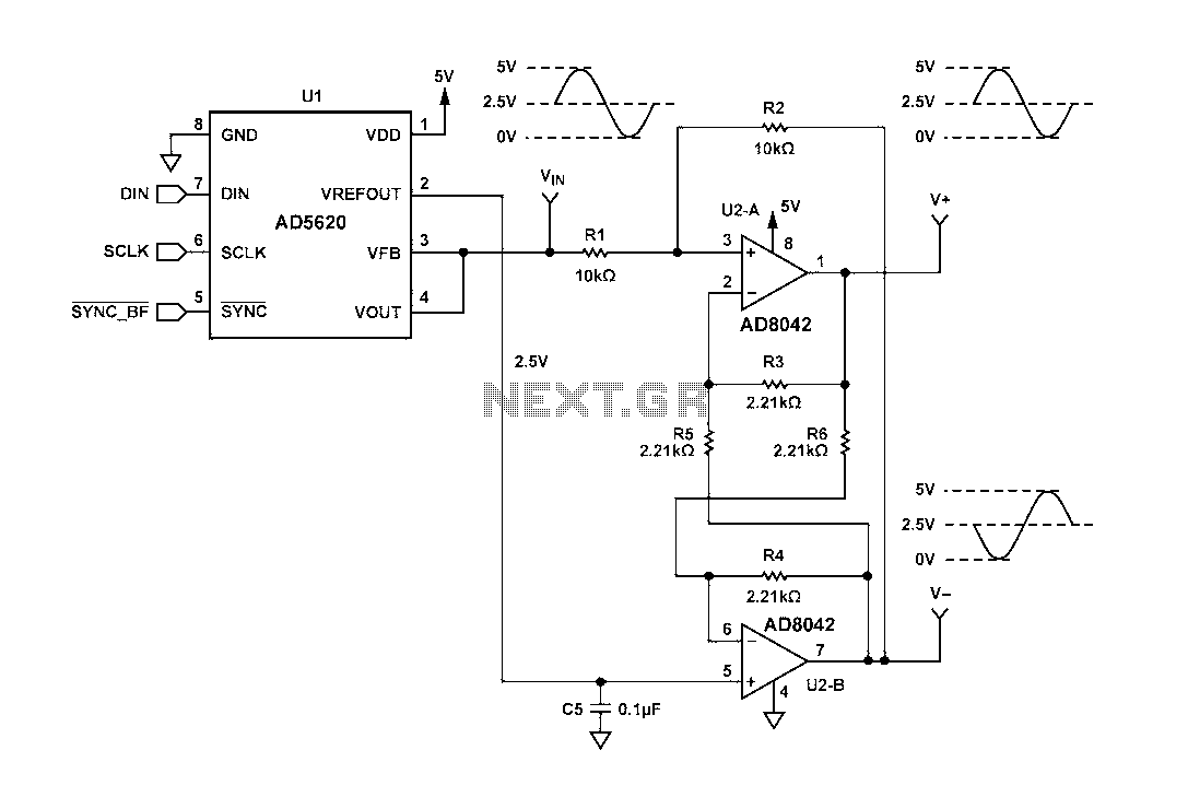
Figure 1 illustrates a circuit that utilizes a single +V power supply and a voltage output Digital-to-Analog Converter (DAC) known as the AD5620. The DAC is controlled via an SPI port, with its output ranging from 0 V to...
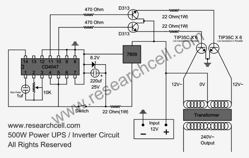
This circuit diagram features a single variable resistor utilized to adjust the frequency of a 240V AC output current. It is advisable to use a frequency meter to modify the frequency from 50Hz to 60Hz according to specific requirements....
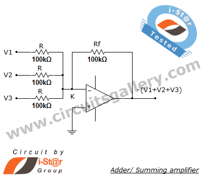
A summing amplifier, also known as an adder, is utilized to combine two or more signal voltages. This voltage adder circuit is straightforward and allows for the addition of multiple signals. It has a wide range of applications in...