
10 Step LED Circuit
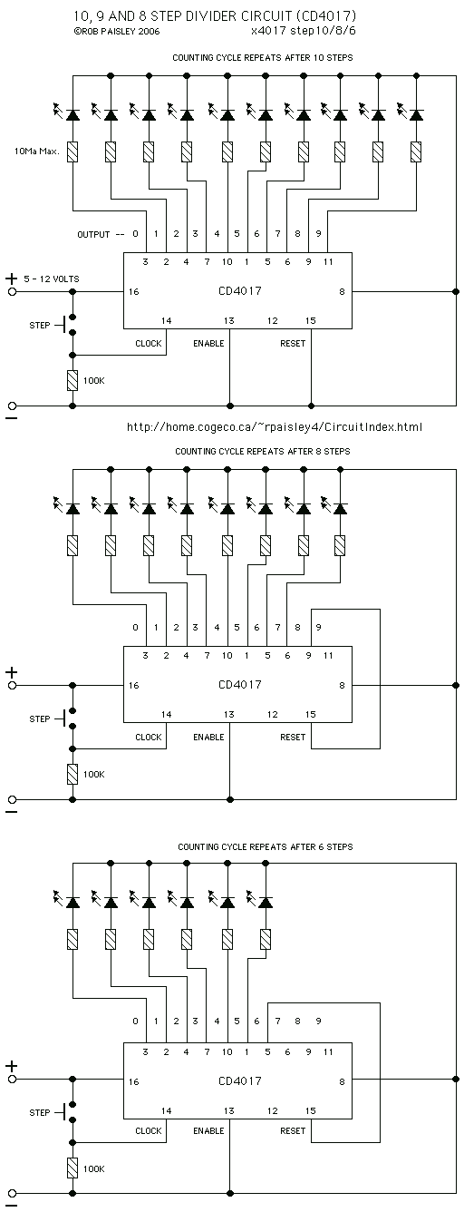
The circuit utilizes a CD4017 decade counter, which is a versatile component designed to count pulses and drive output devices such as LEDs. The operation begins with the closure of switch S1, which triggers the counter to increment its count by one. Each output pin (Q0 to Q9) corresponds to a specific count value and is designed to activate an LED when that count is reached.
The CD4017 has ten output pins, allowing it to count from 0 to 9. When the count reaches 10 (which corresponds to the maximum count of 9 on the output pins), the counter resets automatically, returning to 0 and restarting the counting cycle. This behavior is ideal for applications requiring sequential activation of multiple outputs, such as LED indicators.
In this configuration, each LED is connected to its respective output pin of the CD4017. A current-limiting resistor is typically placed in series with each LED to prevent excessive current flow, which could damage the LEDs. The value of these resistors can be calculated based on the forward voltage drop of the LEDs and the supply voltage used in the circuit.
The reset feature of the CD4017 can be utilized if external control is needed to reset the counter manually. This is accomplished by connecting the reset pin to a switch or another control signal. However, in this basic configuration, the automatic reset functionality suffices for continuous operation.
Power supply considerations must also be taken into account, ensuring that the CD4017 is powered within its specified voltage range (typically 3V to 15V) and that the LEDs are rated for the same voltage or appropriately connected to avoid damage.
Overall, this circuit provides a straightforward method for counting pulses and controlling multiple outputs in a sequential manner, making it suitable for various applications in electronic projects.Each time switch S1 is closed the count on the CD4017 advances by 1 step and the coresponding LED turns on. When the maximium count plus 1 is reached for each circuit the cycle is restarted and repeats. 🔗 External reference
Related Circuits
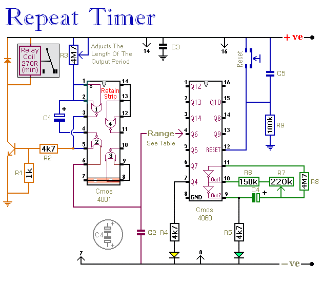
The CMOS 4060 integrated circuit (IC) features two built-in inverters located at pins 9, 10, and 11, which must be interconnected to create an oscillator. The output of this oscillator is available at Pin 9, which continuously alternates between...
It may be necessary to use 10 diodes and various resistors, particularly when utilizing white LEDs. Refer to the Troubleshooting section in step 3 for more details. A sheet of 0.005-inch thick matte drafting film was purchased from a...
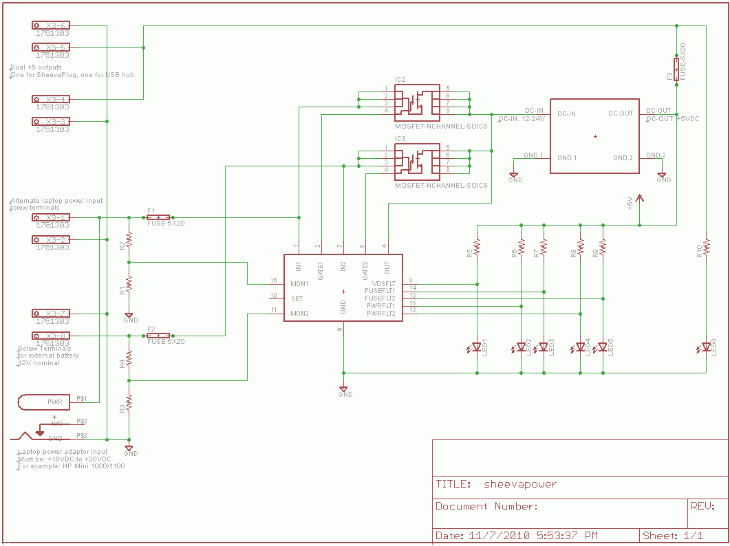
The SheevaPlug is known to have a suboptimal power supply, particularly affecting users in the UK operating at 240VAC. Additionally, heavy loads on the USB can cause issues, especially when connecting an external mechanical disk drive. This project aims...
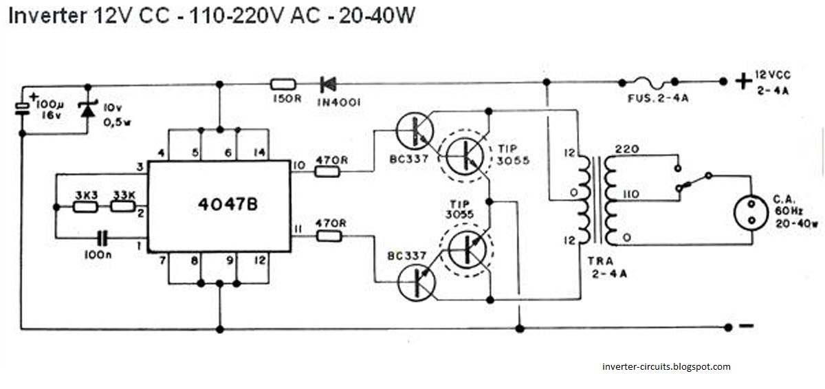
This schematic represents a simple 40W inverter that converts 12V to 220V. It has been functional for four years. The core component of the circuit is a CD4047 integrated circuit (IC) configured as an astable multivibrator. The resistance and...

An intercom utilizing dual-modular wall jacks is depicted in this circuit. If the wires are accessible in the home telephone cable, this system can be installed with minimal difficulty. The intercom system described employs dual-modular wall jacks, which are standard...
The Chizuru 100Hz channel frequency pulse charging circuit for electric bike batteries is designed to manage the charging process efficiently. It features a step-down transformer (Tl) and a bridge rectifier formed by diodes D5 to D8. The output ripple...