
32768 hz quartz oscillator
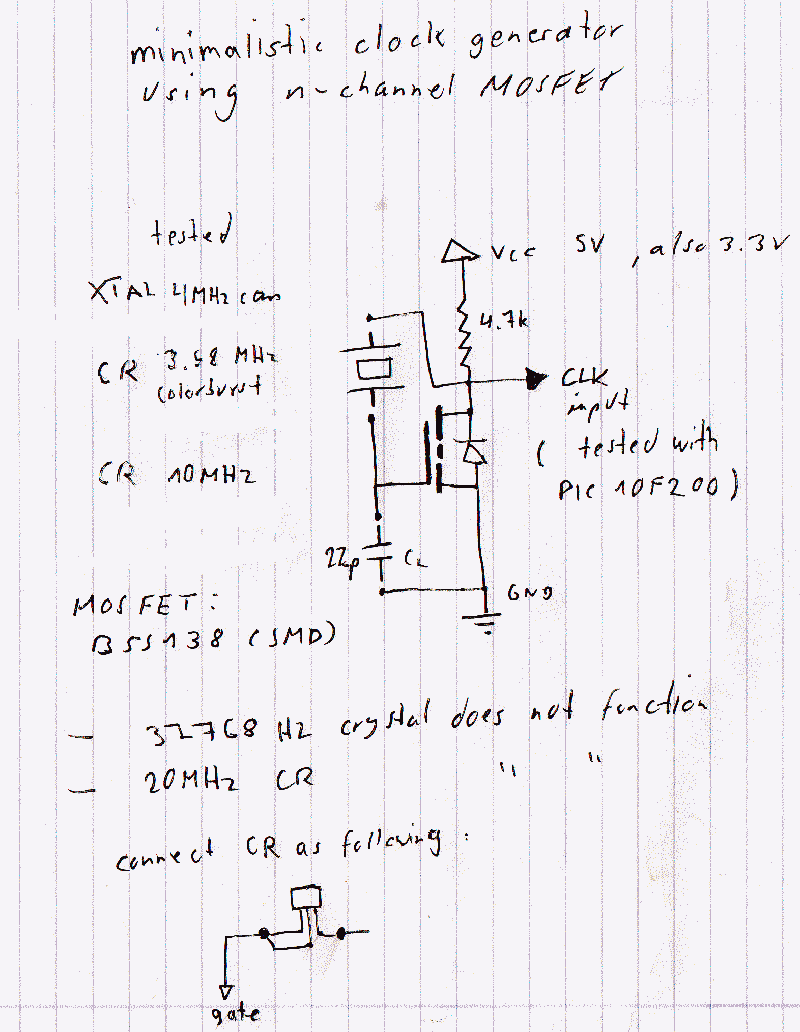
A watch crystal oscillator is a fundamental component used in various electronic applications, particularly in microcontroller circuits, to provide a stable clock signal. In the context of a PIC microcontroller, the oscillator circuit can be designed using a quartz crystal, which is known for its precise frequency stability.
The circuit typically involves connecting a quartz crystal between the oscillator pins of the PIC microcontroller. The crystal's resonant frequency determines the clock speed of the microcontroller, which is crucial for timing and synchronization in digital circuits. The configuration may include load capacitors connected to the crystal terminals to ensure proper operation and frequency stability.
In this design, since the use of logic gates is avoided, the oscillator function relies solely on the internal oscillator capabilities of the PIC microcontroller, which can utilize the external crystal for generating the necessary clock signal. This approach simplifies the circuit and reduces component count, enhancing reliability and minimizing potential failure points.
The typical values for the load capacitors can be calculated based on the crystal specifications and the microcontroller's requirements, ensuring that the circuit operates within the desired frequency range. It is essential to refer to the specific PIC microcontroller datasheet for accurate pin configurations and recommended capacitor values to optimize performance.
Overall, the implementation of a watch crystal oscillator in a PIC microcontroller circuit is a straightforward yet effective method to achieve precise timing without the complexity introduced by additional logic gates.hi this my 1st post here. topic is a watch crystal oscillator for PIC (microcontroller). i do not want to use logic gates. here the circuit (a thread.. 🔗 External reference
Related Circuits
This circuit is a Wien Bridge Sine Wave Oscillator. The primary challenge in generating a low distortion, constant amplitude sine wave is to achieve the appropriate loop gain in the amplifier. By utilizing the 2N3069 JFET as a variable...
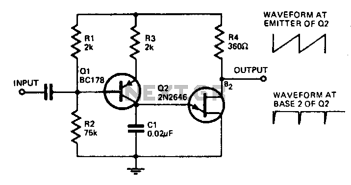
With the component values shown, the oscillator has a frequency of 8 kHz. When an input signal is applied to the base of Q1, the current flowing through Q1 is varied, thus affecting the time required to charge C1....
The figure illustrates a multiple output crystal oscillator, which primarily consists of three gates of Al, four resistors, two capacitors, and a crystal. Resistors R1 to R4 offset two inverters within the linear range and are connected between pin...
The following circuit is a basic 555 square wave oscillator. Features include a 1 kHz tone, simple circuitry, a current limit of 200 mA, reduced inductive voltage, and a supply voltage range of 4.5 to 9 volts. Components used...
The transformer OCL and capacitor C1 create a tank circuit, which is coupled with sufficient turns to drive the grid in the lower left-hand winding. The output circuit is connected through a separate winding. For optimal waveform characteristics in...
This circuit eliminates the traditional tungsten filament lamp amplitude regulator along with its associated time constant and linearity issues. Additionally, it addresses the reliability problems commonly found with lamps. The Wien Bridge oscillator is utilized, leveraging the fact that...