
wien bridge sine wave oscillator circuit using lm107
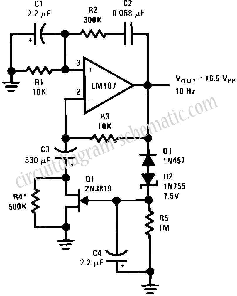
The described circuit functions as a robust oscillator design, utilizing the Wien Bridge oscillator principle to achieve stable oscillations without the reliability concerns associated with traditional filament lamps. The elimination of the amplitude regulator enhances overall circuit performance by removing time constant issues and improving linearity. The Wien Bridge's unique ability to match phase shifts at a specific frequency is pivotal for achieving sustained oscillation.
In this configuration, the positive feedback mechanism is critical, as it allows the circuit to reach the oscillation condition where the feedback signal reinforces the input signal. The incorporation of negative feedback is essential for stabilizing the oscillation frequency, which is vital in applications requiring precision. The careful selection of components, such as diodes D1 and D2, ensures that the circuit can respond quickly to transient conditions, enabling effective charge management for capacitor C4.
The use of C3 as a low-frequency roll-off capacitor is a strategic choice to mitigate the effects of DC offset errors, which can lead to distortion if amplified. The relationship between the open-loop gain of the amplifier and the feedback loop's response time is crucial in determining the overall distortion characteristics of the oscillator. Thus, R5 and C4 must be chosen carefully to optimize the performance based on the desired application.
The adjustment of R4 to maintain a small negative gate bias on the FET is a sophisticated technique that enhances the circuit's stability and performance. This design approach allows for a general-purpose oscillator capable of operating efficiently across a range of frequencies while minimizing distortion and maintaining reliable operation. Overall, this circuit represents a significant advancement in oscillator design, providing a versatile solution for various electronic applications.This circuit is that the traditional tungsten filament lamp amplitude regulator is eliminated along with its time constant and linearity problems. In addition, the reliability problems associated with a lamp are eliminated. The Wien Bridge oscillator is widely used and takes advantage of the fact that the phase of the voltage across the parallel b
ranch of a series and a parallel RC network connected in series, is the same as the phase of the applied voltage across the two networks at one particular frequency and that the phase lags with increasing frequency and leads with decreasing frequency. When this network the Wien Bridge is used as a positive feedback element around an amplifier, oscillation occurs at the frequency at which the phase shift is zero.
Additional negative feedback is provided to set loop gain to unity at the oscillation frequency, to stabilize the frequency of oscillation, and to reduce harmonic distortion. Here is a schematic drawing : The circuit presented here differs from the classic usage only in the form of the negative feedback stabilization scheme.
Circuit operation is as follows: negative peaks in excess of -8. 25V cause D1 and D2 to conduct, charging C4. The charge stored in C4 provides bias to Q1, which determines amplifier gain. C3 is a low frequency roll-off capacitor in the feedback network and prevents offset voltage and offset current errors from being multiplied by amplifier gain. Distortion is determined by amplifier open-loop gain and by the response time of the negative feedback loop filter, R5 and C4.
A trade-off is necessary in determining amplitude stabilization time constant and oscillator distortion. R4 is chosen to adjust the negative feedback loop so that the FET is operated at a small negative gate bias.
The circuit shown provides optimum values for a general purpose oscillator. 🔗 External reference
Related Circuits
This circuit illustrates an FM modulator with a strong and weak signal switching mechanism. The circuit diagram 3-14 (a) depicts mechanical switches, including a worker selector switch that allows for signal strength selection. Figure 3-14 (b) demonstrates the implementation...
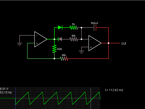
This is the sawtooth wave generator circuit diagram, accompanied by a detailed explanation of its operational principles. An electronic circuit simulator is available to assist in designing the sawtooth wave generator circuit and simulating it online for enhanced understanding. The...
A JFET transistor is utilized as a high-to-low impedance converter and signal mixer. The input impedance is approximately 50.0 kΩ, which can be increased by adjusting resistors R5 to R8 up to 10 MΩ. The output impedance is around...
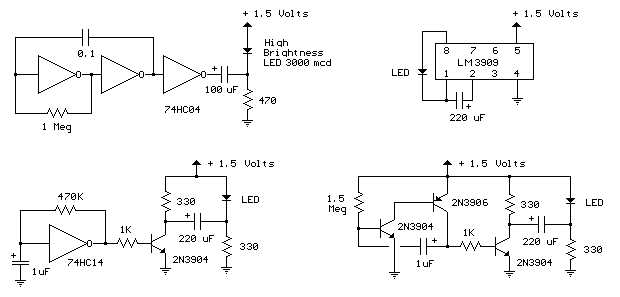
The LED flasher circuits operate on a single 1.5-volt battery. The circuit on the upper right utilizes the popular LM3909 LED flasher IC and requires only a timing capacitor and an LED. The LED flasher circuit using the LM3909 integrated...
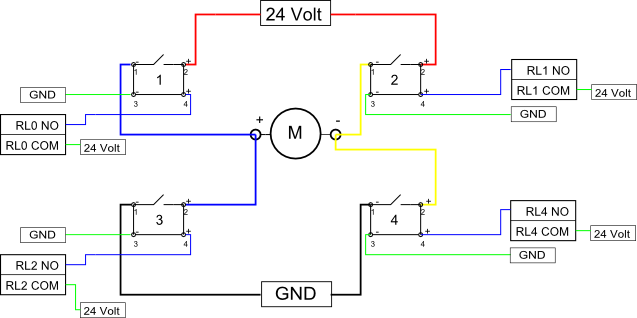
Eight solid-state relays (SSR) and an ADAM-4068 (Serial-I/O device) are utilized to wire a circuit for controlling a motor in a robotic application. The ADAM-6048 is a versatile device that facilitates control of digital inputs and outputs via RS-485...
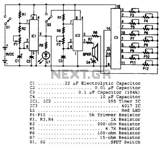
Three integrated circuits (ICs) are utilized to generate sounds. IC1 is a 555 timer configured as an astable multivibrator, producing clock pulses. The frequency of these clock pulses is adjustable via a trimmer potentiometer, P1. These clock pulses are...