
Simple voltage controlled oscillator
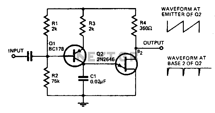
The described oscillator circuit operates at a frequency of 8 kHz, determined by the selected component values. The key component, Q1, functions as a transistor that modulates the current flowing through it in response to an input signal applied to its base. This modulation directly influences the charging time of capacitor C1, which is critical for establishing the oscillation frequency.
The phase inversion characteristic of transistor Q1 is significant; it introduces a 180-degree phase shift between the input signal and the output signal. This means that when the input signal reaches its peak, the output signal is at its trough, effectively inverting the waveform. This behavior is essential in various applications, particularly in timing circuits and waveform generation.
Furthermore, the output from this oscillator can be utilized to trigger a bistable flip-flop. A bistable flip-flop is a type of digital memory circuit that has two stable states and can be used to store binary information. The oscillator's output provides a clock signal that can toggle the state of the flip-flop, allowing for precise control in digital applications, such as counters, registers, or state machines.
In summary, this oscillator circuit not only generates an 8 kHz signal but also offers versatility in digital logic applications by providing a phase-inverted output that can effectively trigger bistable flip-flops. The design's simplicity and effectiveness make it a valuable component in various electronic systems.With the component values shown, the oscillator has a frequency of 8 kHz. When an input signal is applied to the base of Ql the current flowing through Ql is varied, thus varying the time required to charge Cl. Due to the phase inversion in Ql the direction of output frequency change is 180 degrees out of phase with the input signal
The output may be used to trigger a bistable flip-flop. 🔗 External reference
Related Circuits
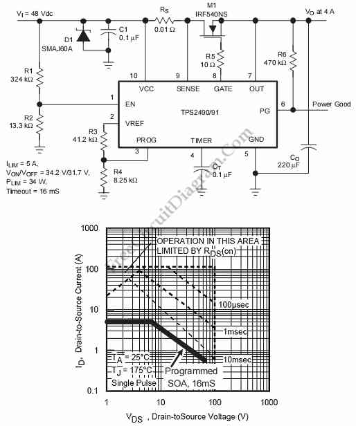
This is a positive high-voltage hot swap controller circuit with a power limiter. This circuit utilizes the TPS2491 or TPS2490, as both of them have specific features. The positive high-voltage hot swap controller circuit is designed to safely connect and...
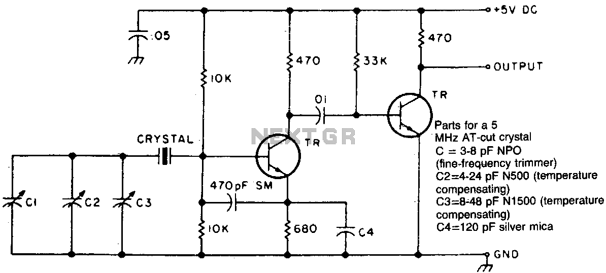
Two different negative-coefficient capacitors are blended to produce the desired change in capacitance to counteract or compensate for the decrease in frequency of the "normal" AT-cut characteristics. The circuit utilizes a combination of two negative-coefficient capacitors to achieve a specific...
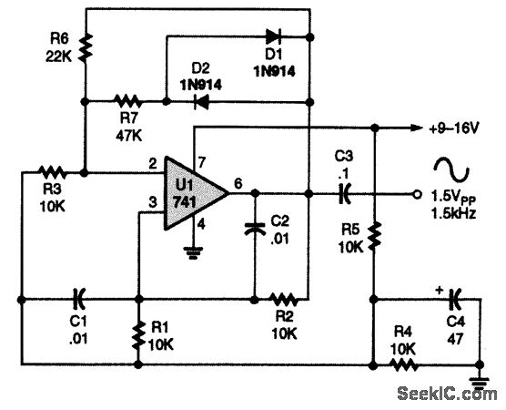
A 741 operational amplifier is configured within a Wien-bridge audio sine-wave oscillator circuit. The components C1, C2, R1, and R2 are responsible for determining the operating frequency of the circuit. By utilizing NPO capacitors and metal-film resistors, the oscillator...
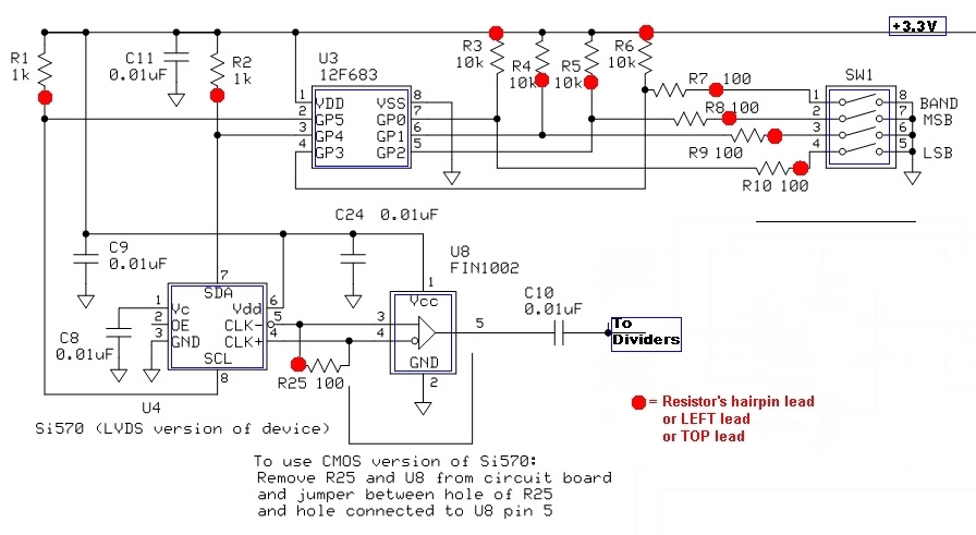
The current draw should be between 80 and 100 mA. The exact value is highly dependent on the Si570, its version (CMOS vs. LVDS), the frequency setting, and variations in the circuit components. The SW1 programming of U3 can...
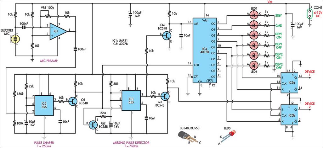
This circuit can switch two or more devices on and off in response to a series of rapid handclaps. The claps are detected by an electret microphone and amplified by a 741 operational amplifier (IC1). IC1 is configured as...
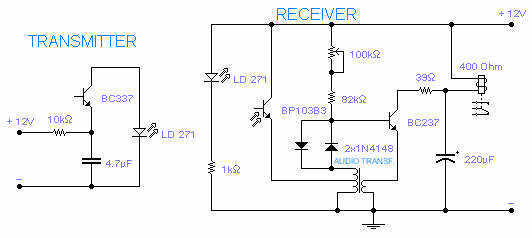
The transmitting section of this infrared tx-rx is unusually simple but it works rather well: the infrared LED pulses at a frequency of 160Hz and its range, with its receiver, is between 2 and 4m depending on the transformer...