
Thyristor controlled forward start circuit
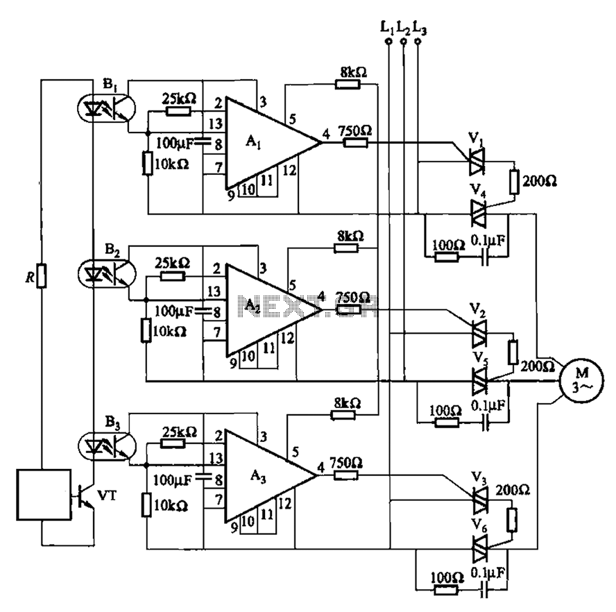
The 331 circuit employs a two-way thyristor, also known as a bidirectional thyristor, which facilitates the control of motor operations through an electronic switching mechanism. This configuration eliminates the need for traditional mechanical contacts, resulting in a significant reduction in wear and tear, thereby enhancing the reliability and longevity of the system.
The circuit is designed to manage the motor's start and stop functions efficiently, utilizing the thyristor's ability to handle high currents and voltages with minimal losses. The absence of contact points not only reduces noise and electrical arcing—common issues in conventional relay-based systems—but also contributes to a cleaner operational environment. This feature is particularly advantageous in applications where noise reduction is critical, such as in residential or sensitive industrial settings.
The thyristor is triggered by a control signal, which can be generated by various means, such as a microcontroller or a simple switch. Upon receiving the trigger signal, the thyristor allows current to flow through the motor, initiating its operation. To stop the motor, the control signal is removed, and the thyristor enters a blocking state, effectively halting the current flow. This process can be repeated as needed, making the circuit ideal for applications requiring frequent start-stop cycles.
In summary, the 331 circuit's design prioritizes efficiency, reliability, and noise reduction, making it well-suited for environments where motors must be operated frequently without the disadvantages associated with traditional electromechanical systems.331 circuit shown in FIG. It uses two-way thyristor controlled motor start and stop. It has no contact, no noise sound, no spark, etc., suitable for frequent operation of the o ccasion.
Related Circuits
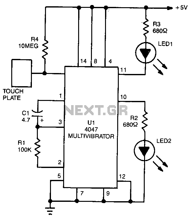
LED1 and LED2 indicators activate and stay illuminated each time the circuit is triggered. During the timing cycle, the Q output at pin 10 of U1 becomes positive when the Q output at pin 11 turns negative. The two...
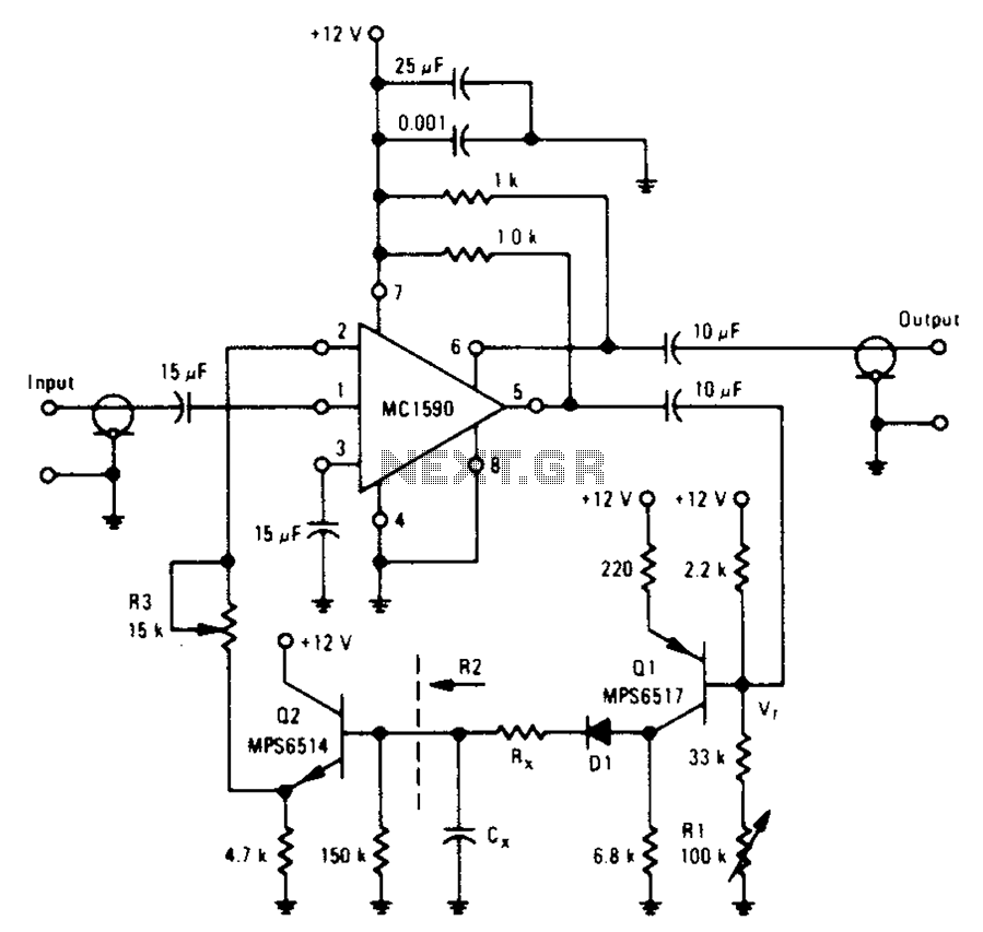
An amplifier designed to achieve a voltage gain of approximately 20, utilizing the MPS6517 PNP transistor in the emitter follower configuration. The RI controller allows for adjustment of the transistor's quiescent point. The output signal is activated only when...
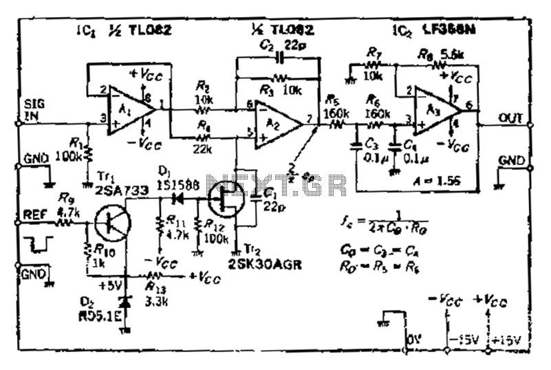
After turning off TT2, the input signal enters through chi Az, where the input resistance is very high and reaches the same potential. The inverting input terminal must also be associated with this movement. Therefore, Trr functions as a...
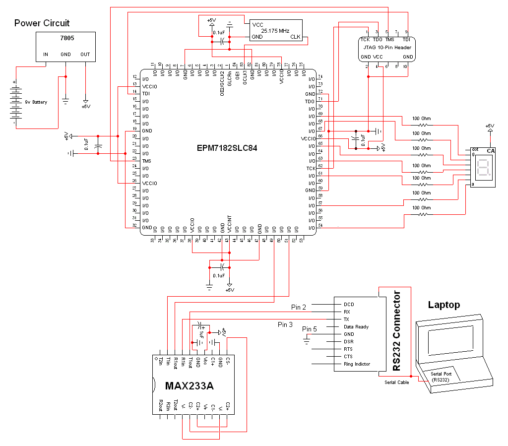
The schematic for this project is a modified version of the CPLD development board schematic. Several new components have been added for this project, and the completed schematic can be viewed below. The main components in the schematic are...
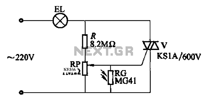
An automatic light control circuit is designed to illuminate a lamp when it is dark and to turn off the light at daybreak. The circuit, as shown in Figure 2-86, employs bidirectional thyristor tubes and features a straightforward design....
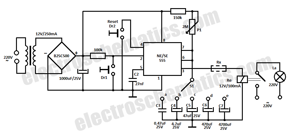
This time delay relay circuit is constructed using the NE/SE555 integrated circuit, manufactured by Intersil, which features a precision timer. The circuit exhibits stability against temperature variations. The NE/SE555 integrated circuit is a versatile timer used in various applications, including...
Warning: include(partials/cookie-banner.php): Failed to open stream: Permission denied in /var/www/html/nextgr/view-circuit.php on line 713
Warning: include(): Failed opening 'partials/cookie-banner.php' for inclusion (include_path='.:/usr/share/php') in /var/www/html/nextgr/view-circuit.php on line 713