
Video Amplifier Circuit for Camera PCB

The described video amplifier circuit is essential for enhancing the video signal quality when interfacing a digital camera with a television. The circuit typically consists of several key components, including transistors, resistors, and capacitors, which work together to amplify the low-level video signal generated by the camera.
The transistor serves as the primary amplification device. In this configuration, it is crucial to select a transistor capable of handling the frequency range associated with video signals, particularly for PAL standards. The circuit's design should ensure that the transistor operates within its linear region to prevent distortion of the video signal.
Resistors are employed to set the biasing conditions for the transistor, allowing it to operate effectively within the desired bandwidth. Additionally, feedback resistors may be included to stabilize the gain of the amplifier and improve linearity. Capacitors are used for coupling and decoupling purposes, ensuring that DC bias levels do not affect the AC video signal while maintaining the integrity of the frequency response.
The 3 dB bandwidth of 5.5 MHz indicates that the amplifier can effectively handle video signals within this frequency range without significant attenuation. This bandwidth is suitable for standard PAL video signals, which typically operate within a frequency range that includes the necessary components for clear image reproduction.
Overall, this video amplifier circuit is a practical solution for connecting a digital camera to a television, facilitating the viewing of captured video clips with enhanced signal strength and clarity. Proper implementation of the circuit will ensure reliable performance and high-quality video output.There are occasions when you want to view your video clips taken in your digital camera on your TV. You can do so by interfacing the camera video output to video input of your TV. But this times you cant connect directly as it needs some amplification before the signal reaches from camera to television. The video amplifier schematic circuit shown in the figure is a simple PAL video amp, expected to have a 3db bandwidth of 5. 5MHz. You can connect your camera to TV through this circuit. So this is a low level transistorized video amplifier stage that accepts 1V (p-p) and outputs 2V(p-p) signal. 🔗 External reference
Related Circuits
A simple USB FM transmitter that can be used to play audio files from an MP3 player or computer on a standard VHF FM radio by connecting it to a USB port. The circuit does not require any coils...
To achieve optimal audio reproduction at varying listening levels, it is essential to adjust tone control settings to align with the established characteristics of human auditory perception. The sensitivity of the human ear changes non-linearly across the entire audible...
Assortment of siren circuits. This month, three different types of siren circuits are being created based on the 555 timer. The first circuit simulates the siren of a British police car. It utilizes two 555 timers. The design of the...
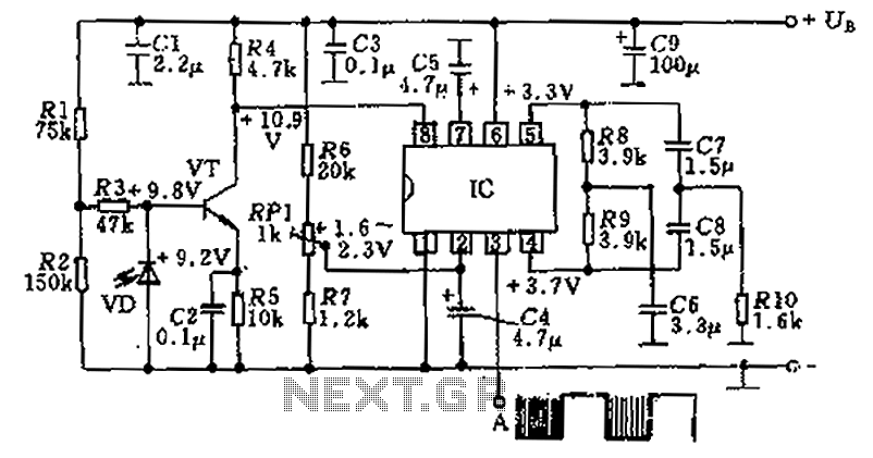
The circuit utilizes an integrated amplifier, resulting in a simple and compact design. The TDA4050 IC is employed, where a weak signal is received by the infrared photodiode (VD) and first passes through a transistor amplifier. The circuit is...
The 200 MHz JFET possesses the following characteristics: 1. Low crossmodulation 2. High large-signal handling capability 3. No requirement for neutralization 4. Automatic Gain Control (AGC) managed by adjusting the biasing of the upper. The 200 MHz Junction Field Effect...
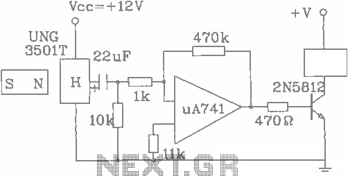
The UGN-3501T Hall sensor features a highly sensitive counter circuit diagram, allowing it to detect very small changes in magnetic fields. This capability enables the detection of ferrous metals. Utilizing this characteristic, it can be employed to count loads....