
3V Battery To 5V Dc/Dc Converter
The described circuit serves as a DC-DC boost converter, facilitating the conversion of a low input voltage from a battery source to a higher output voltage suitable for logic applications. The circuit is designed to efficiently convert 3 V to a stable 5 V output while delivering a current of up to 40 mA, achieving an efficiency of approximately 85%.
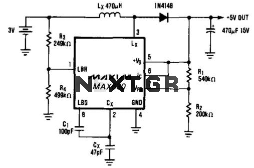
The core functionality is based on a switching regulator topology, where the integrated circuit (IC) plays a pivotal role in controlling the switching of an external inductor. When the IC's pin 6 is driven low, the output voltage is determined by the input battery voltage minus the forward voltage drop across diode D1. This drop is a critical factor to consider, as it directly impacts the output voltage level.
Additionally, the circuit incorporates an optional feature that utilizes capacitor C1, along with resistors R3 and R4, to modulate the oscillator frequency in response to decreasing battery voltage levels. When the battery voltage drops to 2.0 V, the oscillator frequency is reduced. This adjustment is crucial, as it allows the circuit to maintain its output power capability in the face of diminishing input voltage. By lowering the frequency, the peak inductor current increases, which compensates for the reduced input voltage, ensuring that the output remains stable and meets the required specifications for 5-V logic supply.
In summary, this circuit design effectively addresses the challenge of powering 5-V logic devices from lower voltage battery sources, while also incorporating features that enhance performance under varying input conditions. The combination of efficient voltage conversion, output stability, and adaptive frequency response makes this circuit a robust solution for portable electronic applications. A common power-supply requirement involves converting a 2.4- or 3-V battery voltage to a 5-V logic suppl y. This circuit converts 3 V to 5 V at 40 mA with 85% efficiency. When Ic (pin 6) is driven low, the output voltage will be the battery voltage minus the drop across diode Dl. The optional circuitry that uses CI, R3, and R4 lowers the oscillator frequency when the battery voltage falls to 2.0 V.
This lower frequency maintains the output-power capability of the circuit by increasing the peak inductor current, which compensates for the reduced battery voltage. 🔗 External reference
Related Circuits
When the power supply is connected to IC1, the output pin 3 operates at a frequency of 1 kHz. The components Q1 and Q2 work in a push-pull configuration. When a positive output signal is generated, Q1 and Q2...
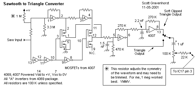
This wave shaper needs an input saw that goes from Vss to (ideally) Vdd. It works well with the 4069 VCO designed by Ren? Schmitz. Any saw will work as long as the wave is centered halfway between the...
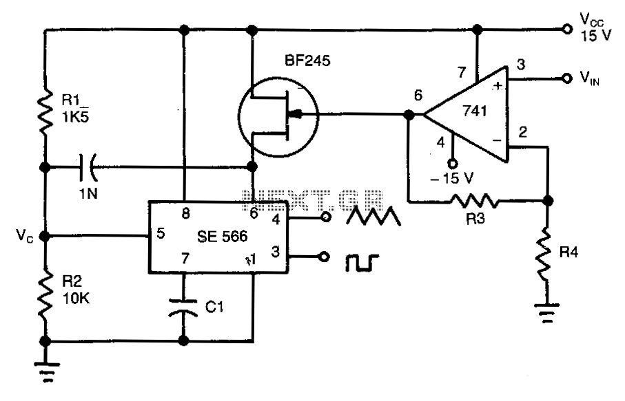
This circuit operates based on the frequency variation of the function generator in relation to the input voltage (ViN). The frequency is influenced by the capacitance and resistor connected to pin 6, with the resistor being substituted by a...
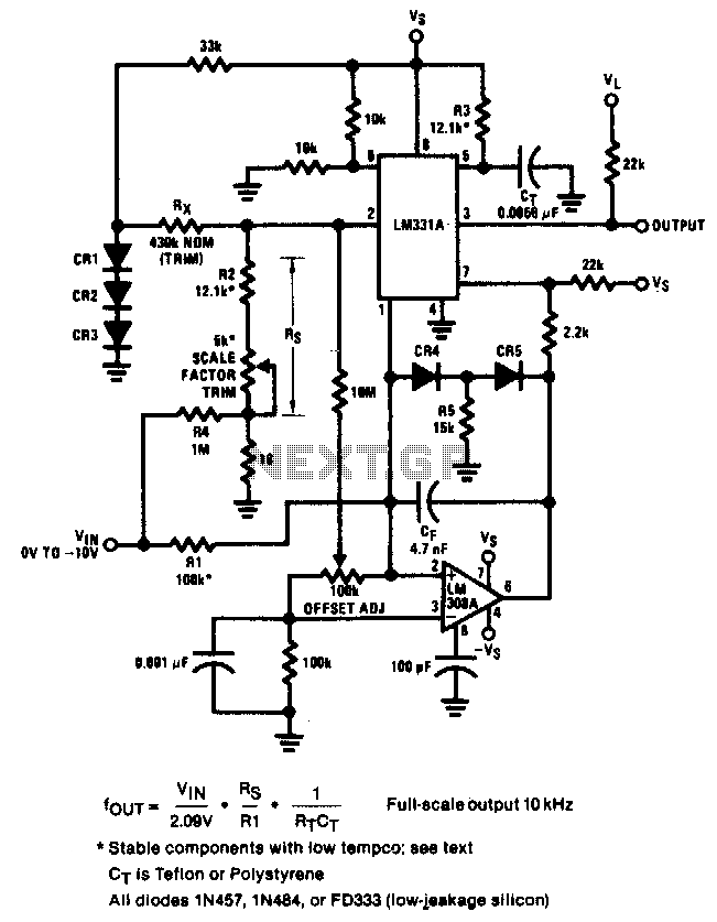
The circuit achieves an error of better than 0.02% and a nonlinearity of 0.003% within a ±20°C range around room temperature. The circuit's design focuses on precision and linearity, making it suitable for applications that require high accuracy in temperature...

An analog-to-digital converter (ADC) transforms an analog input voltage into a digital value. This circuit illustrates the operation of an ADC, utilizing the ATmega8 microcontroller to control its functionality. The resolution of the converter denotes the number of discrete...
The 1956 Regency ATC-1 converter marked the beginning of a new era in amateur radio. This compact converter utilized only two transistors—one PNP and one NPN—both made of germanium and now considered obsolete. However, they represented the onset of...