
3v fm transmitter circuit

The 3V FM transmitter circuit is designed to operate efficiently with minimal components, making it an ideal choice for hobbyists and educational purposes. The circuit consists of two main active components: the first transistor acts as an audio amplifier, while the second transistor operates as a modulator for the RF signal. The electret microphone captures audio input, which is then amplified to a suitable level for modulation.
The Colpitts oscillator configuration is notable for its simplicity and effectiveness in generating stable RF signals. The tank circuit, composed of the coil and trimmer capacitor, is critical for determining the frequency of oscillation. The five-turn coil is wound carefully to avoid coupling with adjacent turns, which could distort the frequency output.
Adjusting the trimmer capacitor allows for fine-tuning of the transmitter frequency. The procedure for tuning involves incrementally adjusting the capacitor while monitoring the FM radio receiver for the clearest signal. The requirement for a minimum distance between the transmitter and receiver is due to the nature of RF transmission, where harmonics can interfere with the clarity of the received signal.
Overall, this circuit exemplifies a practical application of basic electronics principles, demonstrating how audio signals can be transmitted wirelessly across significant distances with simple components. It serves as an educational tool for understanding the fundamentals of radio frequency transmission, modulation techniques, and circuit design.This 3V FM transmitter Circuit is about the simplest and best basal transmitter to body and accept a advantageous transmitting range. It is decidedly able admitting its baby basic calculation and 3V operating voltage. It will calmly access over three floors of an accommodation architecture and go over 300 meters in the accessible air.
The ambit is basically a radio abundance (RF) oscillator that operates about 100 MHz. Audio best up andamplified by the electret microphone is fed into the audio amplifier date congenital about the aboriginal transistor. Output from the beneficiary is fed into the abject of the additional transistor area it modulates the beating abundance of the catchbasin ambit (the 5 about-face braid and the trimcap) by capricious the alliance capacitance of the transistor.
Alliance capacitance is a action of the abeyant aberration activated to the abject of the transistor. The catchbasin ambit is affiliated in a Colpitts Place the transmitter about 10 anxiety from a FM radio.
Set the radio to about about 89 - 90 MHz. Walk aback tothe FM transmitter and about-face it on. Spread the ambagious of the braid afar by about 1mm from anniversary other. No coilwinding should be affecting addition winding. Use a baby spiral disciplinarian to tune the trim cap. Remove the screwdriverfrom the trim spiral afterwards every acclimation so the LC ambit is not afflicted by devious capicitance. Or use a plasticscrewdriver. If you accept adversity award the transmitting abundance again accept a additional being tune up and downthe FM punch afterwards every adjustment.
One abounding about-face of the trim cap will awning its abounding ambit of capacitance from 6pF to 45pF. The accustomed FM bandage tunes in over about one tenth of the abounding ambit of the affability cap.
So it is best to acclimatize it in accomplish of 5 to 10 degrees at anniversary turn. So affability takes a little backbone but is not difficult. The acumen that there charge be at atomic 10 ft. break amid the radio and the FM transmitter is that the FM transmitter emits harmonics; it does not alone afford on one abundance but on several altered frequencies abutting to anniversary other. You should accept little adversity in award the Tx abundance back you chase this procedure. 🔗 External reference
Related Circuits
This circuit will activate a relay when light falls to a preset level. Light level can be adjusted with VR1 and the relay contacts may be used to operate an external light or buzzer. More: The light sensor used...
A brief background is provided, indicating a basic understanding of electronics, including knowledge of component functions and schematic reading, but lacking further expertise. The circuit in question appears to involve fundamental electronic components, which may include resistors, capacitors, diodes, transistors,...
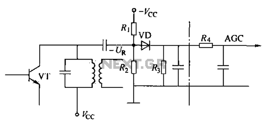
Commonly referred to as an automatic gain control (AGC) circuit, it is primarily utilized in receivers. This circuit maintains a constant output voltage amplitude despite variations in the input signal amplitude. It ensures that the receiver can effectively process...
This circuit will allow you to connect any tape recorder that has a mic and remote input to a phone line and automatically record both sides of a conversation whenever the phone is in use. You will need to...
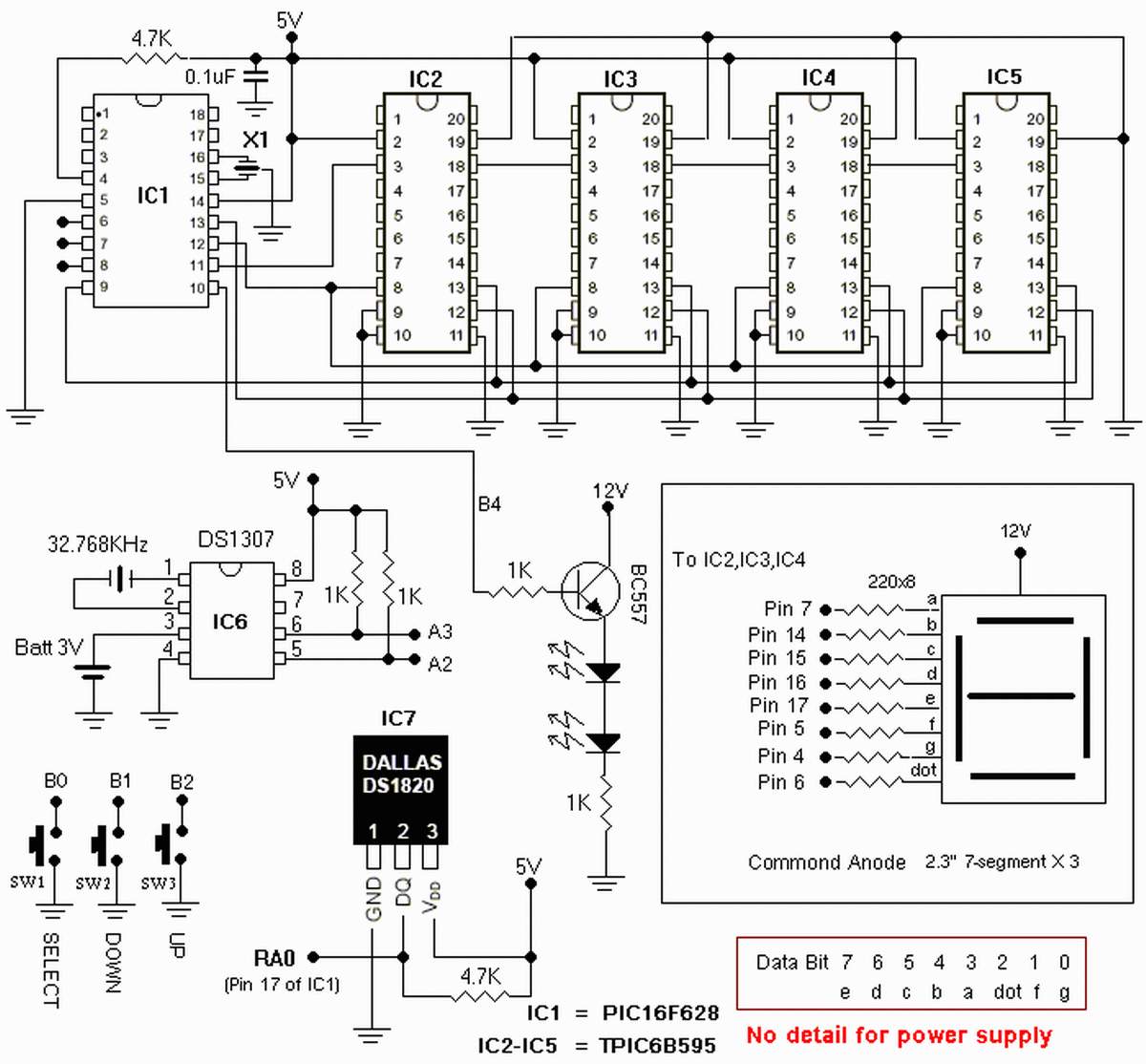
The clock is based on the PIC16F877 microcontroller from Microchip Technology Inc., which performs all of the logic necessary to decode the MSF signal and display the time on twelve 7-segment displays. The circuit design incorporates the PIC16F877 microcontroller, a...
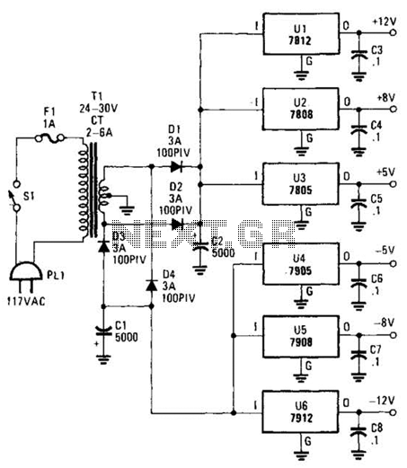
This dual-polarity, multivoltage power supply can be constructed with a minimal investment. The circuit utilizes 78XX and 79XX series voltage regulators, four 3-A diodes, a 24-30 V, 2-6 A transformer, and eight filter capacitors. The described dual-polarity, multivoltage power supply...