
Telephone Record Control Circuit
This circuit is designed to facilitate the automatic recording of telephone conversations by utilizing a tape recorder equipped with a microphone and remote input. The primary components of the circuit include a field-effect transistor (FET) and two additional transistors, designated as Q2 and Q3. The operation of the circuit hinges on the voltage levels present on the phone line, which vary depending on whether the phone is in use or not.
In the idle state (on hook), the phone line maintains a voltage of approximately 48 volts DC. Under these conditions, the FET remains in the off state, which in turn keeps transistors Q2 and Q3 also in the off state, preventing any current from reaching the tape recorder. This ensures that the recorder remains inactive and does not record any background noise or unintended audio.
When the phone is taken off hook, the line voltage drops to below 10 volts DC. This change in voltage activates the FET, switching it into the on state. As a result, transistors Q2 and Q3 are also turned on, allowing current to flow to the tape recorder. It is critical that the tape recorder is pre-set to the record mode, as this ensures that any audio from the conversation will be captured immediately upon activation.
Before installation, it is essential to assess the polarity of both the phone line and the tape recorder's remote input. Proper connections must be made according to the determined polarities to ensure correct functionality and to avoid damage to the components. The circuit effectively harnesses the phone line as a power source, eliminating the need for an external power supply, which simplifies the setup and enhances portability.
This automatic recording circuit provides a practical solution for users needing to document conversations while ensuring ease of use and reliability.This circuit will allow you to connect any tape recorder that has a mic and remote input to a phone line and automatically record both sides of a conversation when ever the phone is in use. You will need to take a couple of voltage readings before connecting the circuit. First determine the polarity of your phone line and connect it to the circuit as shown and then determine the polarity of the remote input and connect it to the circuit.
Circuit operation is as follows. When the phone is on hook the voltage across the phone line is about 48volts dc. When the phone is off hook the voltage will drop to below 10volts dc. When the line voltage is at 48volts the FET is off which causes Q2 and Q3 to be off. When the phone is picked up the FET turns on along with Q2 and Q3 which turns your recorder on. The tape recorder must be in the record mode at all times. As you can see the power source for the circuit is the phone line. 🔗 External reference
Related Circuits
This circuit is a motion detection sensor that utilizes a light source and detector as an infrared motion detector. The motion sensor employs an infrared LED and a phototransistor. Since it relies on light, the sensor's sensitivity can be...

A South African company has developed a 5-kilowatt Fuel Free Generator and discovered that the longevity of the batteries is significantly affected by the process. There are various types of batteries available for testing, including different lead-acid batteries, gel...
This unit captures the ATV signal by sampling the transmission line with minimal insertion loss. It features two N connectors for input and output connections, and a BNC connector is utilized for the video output. The detected output is...
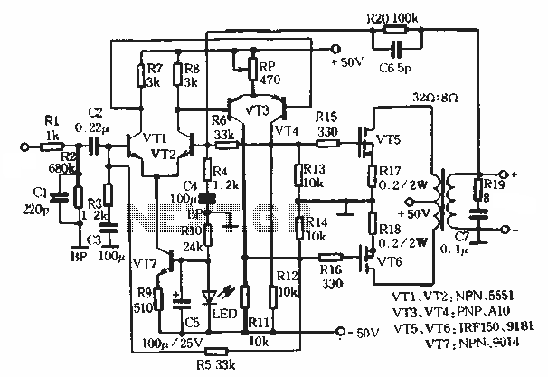
This article describes a transformer-based output FET amplifier, with tonal characteristics similar to those of tube amplifiers. It introduces various effects that are significant for audio enthusiasts. Power amplifier specifications include a rated output power of 50W (with an...

The thermostat electric circuit operates as depicted in the figure. It has three settings: off, low power (Lo), and high power (Peru HL). When the DIP switch SA is set to the Lo position, 220V AC is directed through...
This file contains a schematic for a simple wiretap and instructions for connecting a small tape recorder control relay to the phone line. The discussion begins with an overview of various types of taps, including transmitters, wired taps, and...
Warning: include(partials/cookie-banner.php): Failed to open stream: Permission denied in /var/www/html/nextgr/view-circuit.php on line 713
Warning: include(): Failed opening 'partials/cookie-banner.php' for inclusion (include_path='.:/usr/share/php') in /var/www/html/nextgr/view-circuit.php on line 713