
Dark Activated Switch circuit
The circuit described is a light-activated relay switch utilizing an ORP12 photocell as the light sensor. The primary function of this circuit is to monitor ambient light levels and activate a relay when the light intensity drops below a predetermined threshold. This capability is useful for applications such as automatic lighting control or alarm systems.
The core component, the ORP12 photocell, exhibits a significant change in resistance based on the intensity of light it detects. Under bright conditions, the resistance can drop to approximately 80 ohms, allowing current to flow freely through the circuit. Conversely, in low-light conditions, specifically at around 50 lux, the resistance increases to over 1 megohm, effectively limiting the current flow. This characteristic enables the circuit to differentiate between varying light levels.
The adjustment of the light sensitivity is facilitated by a variable resistor (VR1), which allows for fine-tuning of the light threshold at which the relay is activated. The resistance value of VR1 can be selected to achieve the desired sensitivity, ensuring that the relay will respond appropriately to the ambient light conditions.
Upon reaching the set light level, the circuit activates a relay, which can then control external devices such as lights or buzzers. The relay contacts are rated to handle the load of the connected devices, providing isolation between the low-power sensing circuit and the higher power loads.
In summary, this circuit effectively combines a light sensor and a relay to create an automated response to changes in ambient light, enhancing functionality in various applications where light control is necessary. Proper selection of components and careful calibration of the sensitivity will ensure reliable operation in the intended environment.This circuit will activate a relay when light falls to a preset level. Light level can be adjusted with VR1 and the relay contacts may be used to operate an external light or buzzer. The light sensor used is the ORP12 photocell. In bright light the resistance of the ORP12 can be as low as 80 ohm and at 50lux (darkness) the resistance increases to over 1 Mohm. The 1M control should provide a wide range for light intensities, if not its 🔗 External reference
Related Circuits
This design is based on one published by Milan Lulic in the German magazine elektroModell. Mr. Lulic's design is for surface mount technology (SMT) construction, whereas mine uses standard off-the-shelf components, and is therefore better suited to construction by...

The inverting input is maintained at a low level via a 10K resistor when the circuit is powered on but not in use. During measurement activities, including calibration measurements where the input is floating, this resistor is disconnected. The...
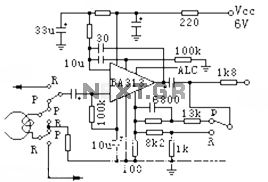
The BA313 is an integrated automatic level control (ALC) circuit designed for use in audio recording preamplifier applications. It is commonly found in cassette tape recorders and comes in a 9-pin dual in-line package (DIP). The circuit features a...
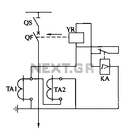
Operating power protection devices can be categorized into two types: DC power supply operation and AC operation. AC operating power is favored due to its lower investment costs, simpler operation, and reliable secondary circuit maintenance, making it widely used...
The south circuit consists of four parts, arranged in descending order: an NPN transistor dynamic garbage device (T1), a PNP transistor differential amplifier (T2, T3) forming a double differential circuit, two balanced output amplifiers with opposite phase, and a...
This document does not aim to provide an extensive account of the integrated circuits (ICs) used in this circuit. For additional information on this topic, please refer to the "Flip-Flop Made With A LM556 Timer Chip" section and the...