
3V Lamp Brightness Controller circuit diagram
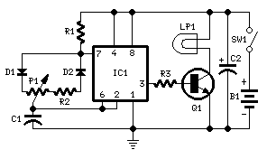
The circuit operates by generating a square wave signal that modulates the power supplied to the light bulb, allowing for precise control of brightness. The integrated circuit (IC1) is the heart of the circuit, producing a stable 150Hz signal. The duty cycle of this signal is adjustable through the potentiometer P1, which alters the width of the output pulses. The narrow pulses, when P1 is turned towards D1, result in minimal power being delivered to the lamp LP1, effectively turning it off. Conversely, as P1 is adjusted towards R2, the pulse width increases, allowing more power to flow to the lamp, thereby increasing its brightness.
Transistor Q1 acts as a switch that is controlled by the output from IC1. When the pulses are narrow, Q1 remains off, preventing current from flowing through the lamp. As the duty cycle increases, Q1 turns on more fully, allowing greater current to flow through LP1, illuminating it to its maximum brightness. The resistor R2 serves a crucial role in limiting the maximum voltage across the lamp to a safe 1.5V, which is necessary to prevent damage to the bulb while ensuring optimal performance. The value of R2 must be selected based on the specific characteristics of the light bulb being used, taking into account the total current draw to maintain the desired voltage level across the bulb leads.
This circuit is particularly useful in applications where variable lighting is essential, such as in photography or in environments where mood lighting is required. By providing an easy-to-use interface through the potentiometer, users can achieve the desired brightness level quickly and efficiently. Overall, this circuit exemplifies effective use of basic electronic components to achieve a practical and functional lighting solution.Here`s a circuit diagram for setting the brightness of the light bulb. You simply use the second battery to make the fruits of this circuit works. Example usage of this circuit is to adjust the brightness of images for close-up photo shoot with a digital camera. IC1 works to generate 150Hz square wave which having a variable duty-cycle. When poten siometer P1 is fully rotated towards D1, the output positive pulses appearing at pin 3 of IC1 are very narrow. Lamp LP1, driven by Q1, is off as the voltage across its leads is too low. When potensiometer P1 is rotated towards R2, the output pulses increase in width, reaching their maximum amplitude when the potentiometer is rotated fully clockwise.
In this way the lamp reaches its full brightness. R2 limits the output voltage, measured across LP1 leads, to 1. 5V. Its actual value is dependent on the total current drawn by the bulb(s) and should be set at full load in order to obtain about 1. 5V across the bulb(s) leads when potensiometer P1 is rotated fully clockwise. 🔗 External reference
Related Circuits
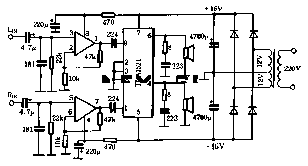
The first power amplifier circuit illustrated in Figure 5-88 utilizes the NE5532 operational amplifier, configured as a line amplifier, and features the TDA1521 power amplifier. This circuit operates with a dual power supply and eliminates the need for coupling...

By introducing a small amount of noise to a signal intended for digitization (approximately 0.7 bits), where n represents the number of bits, for instance, an 8-bit signal with a peak-to-peak voltage of 2 V would result in a...
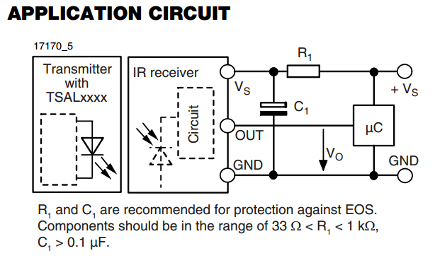
There is an interest in starting an introductory electronics project using an infrared (IR) sensor, but there is some confusion regarding the application circuit provided in the datasheet. The recommended resistor value is significantly lower than the calculated value....
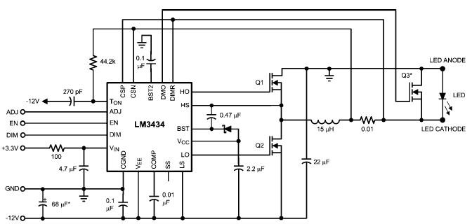
The LM3434 adaptive constant on-time DC/DC buck (step-down) constant current controller can be used to design a simple high-power LED driver application. The LM3434 provides a constant current for illuminating high-power LEDs. The output configuration allows the anodes of...

Detecting electrical equipment sometimes requires disconnecting the circuit in series for more accurate measurements of electrical current using an ammeter. However, restoring the circuit to its original state is necessary, as it can affect the normal operation of electrical...
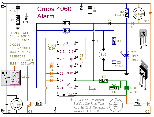
This is a single-zone alarm system featuring automatic exit, entry, and siren cut-off timers. It is designed to accommodate various types of normally-closed input devices, including magnetic reed contacts, foil tape, and passive infrared sensors (PIRs). Additionally, it is...