
Walkman splice power production circuit
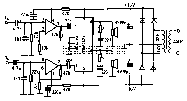
This power amplifier circuit is designed to provide high fidelity audio amplification while maintaining simplicity in construction, making it suitable for amateur audio enthusiasts. The NE5532 operational amplifier is renowned for its low noise and high-performance characteristics, which contribute to the overall sound quality of the amplifier. The TDA1521 is a robust power amplifier capable of delivering substantial output power with minimal distortion, making it an ideal choice for driving speakers in various applications.
The elimination of coupling capacitors in this design not only simplifies the circuit but also improves the bass response by allowing lower frequencies to pass through without attenuation. The output stage of the amplifier is protected against short circuits and overheating, which enhances the reliability of the circuit during operation. With a power supply voltage of 16V and a load impedance of 8 ohms, the amplifier achieves an output power of around 21 watts, which is suitable for driving typical home audio speakers.
The power supply circuit is designed to convert the transformer’s secondary voltage of 2 x 12V into a stable 16V output through rectification and filtering. This ensures that the amplifier receives a consistent voltage level, which is crucial for maintaining performance and minimizing distortion. The shared power supply for both the NE5532 and the TDA1521 simplifies the overall design, reducing component count and potential points of failure.
In summary, this amplifier circuit exemplifies a well-engineered solution for audio amplification, combining effective design principles with high-quality components to deliver superior audio performance. Its ease of construction and reliability make it an excellent choice for both amateur and professional audio applications.The first power amplifier circuit shown in Figure 5-88. Using the "op amp of the Emperor" NE5: 5 32 5 times for line amplifiers, power amp choice Manifold TDAI5210 TDA1521 fidelity OCL dual power supply, the output of this circuit eliminates the need for a coupling capacitor homes, can be extended bass response. When the supply voltage is 16V, RL = 8, fl, an output power of about 2 1 SW. At this point there is only the distortion output short circuit and thermal protection within 0.5% 6TDA1521, provide convenience for amateur production. As shown in Figure 5-88 is to the right of the power supply circuit, the transformer secondary voltage of 2 12V, after the rectifier filter output voltage is 16V, directly connected to the amplifier for electricity.
NE5532 power supply and amplifier share the same power a
Related Circuits
The Wien-Bridge oscillator meets specific requirements due to the presence of a low-pass filter, a high-pass filter, and a 180-degree phase shift from the feedback networks connecting the input to the output. This configuration results in a total phase...
This LED flasher circuit is a classic two-transistor flip-flop. It is a popular circuit often built by beginners in the electronics hobby. The schematic diagram of this well-known LED flasher circuit includes two transistors, two capacitors, four resistors, and...
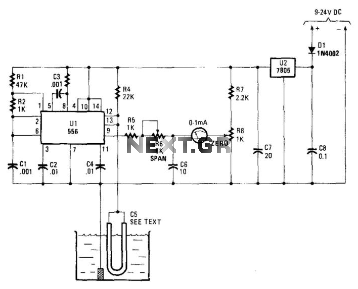
Using a capacitor sensor to detect water levels is a straightforward sensing method. This circuit employs C5, which consists of 10 to 20 inches of #22 enameled wire as one of the electrodes. The oscillator, an NE556 timer, experiences...
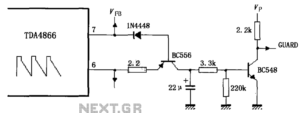
As illustrated in FIG TDA4866, the circuit consists of an external signal generator circuit protection. The internal protection circuit's role is to manage control, while the external protection circuit performs its functions. During normal operation, the vertical amplitude of...
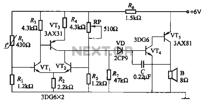
A negative temperature coefficient thermistor is utilized as the temperature sensing element (Rt). The circuit includes a resistor (Ri), a resistor (Rs), a potentiometer (RP), and the thermistor (R) to form a temperature bridge. A differential amplifier is created...
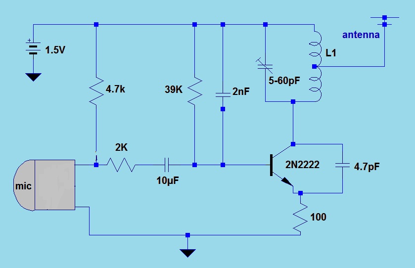
This simple FM (frequency modulation) transmitter is powered only by a 1.5V battery and utilizes a single transistor. The frequency of this transmitter is controlled by the L-C resonance circuit and operates within a range of 80 to 110...
Warning: include(partials/cookie-banner.php): Failed to open stream: Permission denied in /var/www/html/nextgr/view-circuit.php on line 713
Warning: include(): Failed opening 'partials/cookie-banner.php' for inclusion (include_path='.:/usr/share/php') in /var/www/html/nextgr/view-circuit.php on line 713