
High Voltage Stun Guns
Construction of T2: This portion of the project may be considered tedious. As it is unlikely to find pre-made components in stores, it is necessary to build them. The required materials include enamel copper wire (0.20 mm or 0.125 mm), a ferrite stick, and LDPE sheets (0.25 mm). The ferrite stick should be secured with a layer of LDPE (polyethylene; electrical insulating tape can be used as an alternative) and glued or taped in place. Approximately 200-250 windings of wire should be placed on the LDPE (more windings may be added if the stick exceeds 1 meter in length). Following this, another layer of LDPE should be applied, and an additional 200-250 windings should be added, continuing this process to achieve 5-6 layers (approximately 1000-1400 turns). While more turns may enhance performance, care must be taken to avoid internal arcing, which can damage the device. After insulating the assembly, the primary winding should be added, consisting of 15-20 turns of 1 mm wire. Excessive windings can result in higher resistance and inductance, leading to reduced current and smaller spikes in the T2 secondary due to slower rise times. Conversely, too few turns will not adequately saturate the core. MKP capacitors are preferred for their low equivalent series resistance (ESR) and equivalent series inductance (ESL), making them widely used in Tesla coils as multi-capacitor modules (MMC).This device produces high voltage pulses discrupting muscles and nervous sYstem, leaving anyone who touches it in a state of menthal confusion. Can be used agains ferocious animals or attackers, BUT REMEMBER, this device may be illegal in your state (for eg where I live, these devices are banned).
It is quite dangeros for peoples experiencing cardiac problems, and for electronic equipment (like peacemakers), since it generates some RF. Don`t attept irresponsible actions with this device, it is not a toy. The 555 IC is wired as a astable to produce square wave with adjustable freq and duty cycle (notice the potentiomenters and diode). This square wave is feed to a IRF840 Mosfet (no need of totem transistors since freq is low and the IC has enough current capability to rapidly charge/discharge the gate).
As a substitute of the mosfet, a bipolar transistor can be used (and a 100ohm resistor between 555 and base of the transistor). Valid BJT can be BU406, but also smaller BJT can be ok, keep in mind that it must handle at least 2A continuous.
The inductive kick snubber isn`t needed because the power is low and it is almost totally adsorbed to charge the tank capacitor, in addition since this device is battery operated we don`t want to dissipate the power on a resistor but we want it in sparks. With a snubbing network you will experience lower firing rates. USE A PUSHBUTTON SWITCH FOR SAFETY Construction of T2: this is the real boring part. Since it is unlikely to find it in shops we need to build them. Materials needed: enamel copper wire (0, 20 mm or 0, 125 mm), ferrite stick, LDPE sheets (0, 25 mm). Secure the ferrite stick with a layer of ldpe (polyethilene, as a substiture use electric insulating tape) and glue it (or tape it) Place 200-250 windings on the ldpe (even more windings if the stick is more than 1`), another ldpe layer, another 200-250 windings and so on to finally have 5-6 layers (approx 1000-1400 turns but even more doesn`t hurt performance, but be careful for internar arcing that will ruin it).
Insulate it again and place the primary winding, 15-20 turns of 1mm wire are just ok, too much windings (too mush resistance and inductance) will lead to smaller current and smaller spike in T2 secondary because of lower rise time, and too few will not saturate the core. I chosen MKP capacitors because they have low ESR and ESL (they are widely used in tesla coils as mmc capacitors).
🔗 External reference
Related Circuits
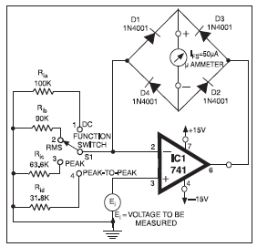
The full-scale deflection of the universal high-input-resistance voltmeter circuit depends on the position of the function switch. The term IFS in the equations refers to the meter's full-scale deflection current rating in amperes. It is important to note that...
This voltage-to-current converter utilizes three operational amplifiers to control a pair of power transistors. The output current is determined by the formula: IOUT = Vin/R6. The output resistance exceeds 50 MΩ, and the output current can vary from 1...
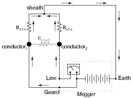
Most ohmmeters of the design shown in the previous section utilize a battery of relatively low voltage, usually nine volts or less. This is adequate for measuring resistances under several mega-ohms (MΩ), but when extremely high resistances need to...
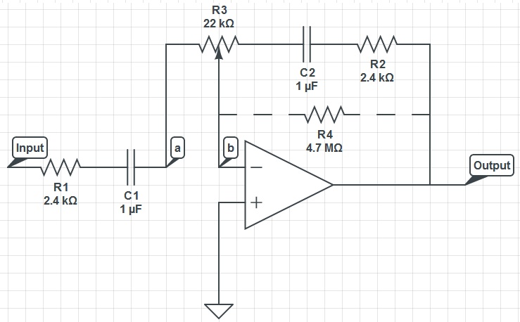
This circuit can function as a treble control circuit, with high-frequency gain occurring when resistor R3 is set to a value that makes points a and b equal (denoted as k=0). Conversely, high-frequency attenuation occurs when R3 is set...
This high voltage converter circuit operates from a 30-volt power supply and can output a voltage ranging from 0 to 3 kV in version 1 or from 0 to 10 kV in version 2. The high voltage converter circuit is...
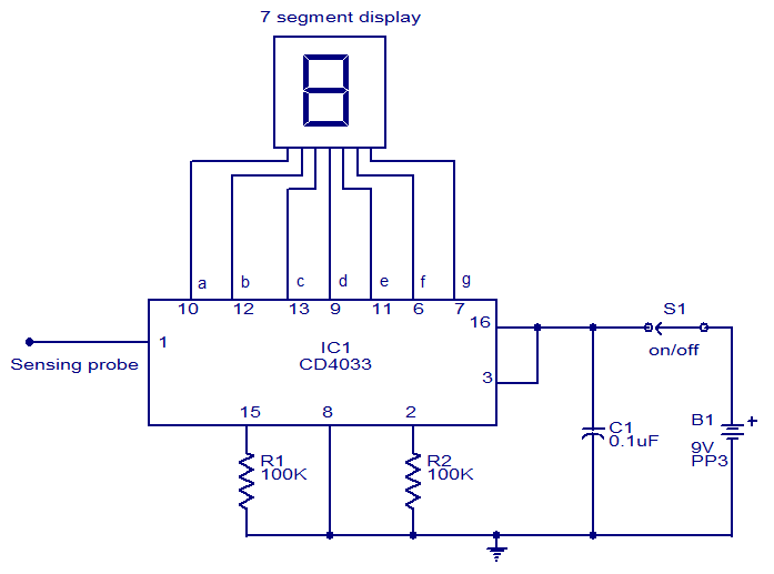
This circuit is designed to test the presence of mains voltage without direct electrical contact with the mains line. The core component of this circuit is the CMOS IC CD4033, which features a five-stage decade Johnson counter and an...