
Two-LED Voltage Indicator
This circuit utilizes the CMOS 4093 IC, which contains four NAND gates configured as Schmitt triggers, allowing for clean transitions and stable oscillation. The primary oscillator function is achieved through the configuration of IC1.A, where the frequency can be adjusted by varying the resistor values. The triangular waveform generated at the junction of R2 and C1 is pivotal for controlling the LED color output. The complementary outputs from IC1.C and IC1.D ensure that the LEDs are driven in a manner that visually represents the charge level through color mixing.
The use of a zener diode in conjunction with a dropper resistor is essential for maintaining a stable supply voltage to the IC, especially when the circuit is powered directly from the car battery. This ensures consistent operation across varying battery voltages. The circuit's adaptability to different supply voltages is a significant advantage, allowing it to be used in various applications beyond battery monitoring, such as simple indicators for temperature or liquid levels.
The design emphasizes simplicity and low cost, making it suitable for hobbyist projects and educational purposes. The ability to visually indicate varying levels through color change provides an intuitive understanding of the monitored parameter, enhancing user experience. The circuit can be further refined or expanded by incorporating additional sensors or modifying component values to tailor its performance to specific applications.There are many applications where the accuracy of a digital or analogue (bar graph) is not required but something better than a simple low/high indicator is desirable. A battery charge level indicator in a car is a good example. This simple circuit requiring only two LEDs (preferably one with a green and red LED in a single package), a cheap CMOS
IC type 4093 and a few resistors should ful-fil many such applications. With a suitable sensor, the indicator will display the relevant quantity as a colour ranging from red through orange and yellow to green. IC1. A functions as an oscillator running at about 10 kHz with the component values given, although this is not critical.
Assuming for the moment that R1 is not commented, the output of IC1. A is a square wave with almost 50% duty cycle. The voltage at the junction of R2 and C1 will be a triangular wave (again, almost) with a level determined by the difference in the two threshold voltages of the NAND Schmitt trigger gate IC1. A. IC1. B, IC1. C and IC1. D form inverting and noninverting buffers so that the outputs of IC1. C and IC1. D switch in complementary fashion. With a 50% duty cycle, the red and green LEDs will be driven on for equal periods of time so that both will light at approximately equal brightness resulting in an orange-yellow display.
With R1 in circuit, the actual input voltage to IC1. A will consist of the triangular waveform added to the dc input Vin. As the input voltage varies, so will the oscillator duty cycle causing either the red or the green LED to be on for longer periods and so changing the visible colour of the combi-LED. The actual range over which the effect will be achieved is determined by the relative values of R1 and R2, enabling the circuit to be matched to most supply voltages.
With the component values given and a supply of 8 volts, the LED will vary from fully red to fully green in response to input voltages of 2. 5 V and 5. 6 V respectively. To monitor a car battery voltage, the battery itself could be used to power the circuit provided a zener diode and dropper resistor are added to stabilise the IC supply voltage.
This is shown in dashed outlines in the circuit diagram. With an 8. 2 V zener the dropper resistor should be around 220 and R1 has to be reduced to 4. 7 k. The LED brightness is determined by R4. As a rule of thumb, R4 = (Vsupply 2) / 3[k] and remember that the 4093 can only supply a few mA`s of output current. Applications of this little circuit include non critical` ones such as go/non-go battery testers, simple temperature indicators, water tank level indicators, etc.
🔗 External reference
Related Circuits
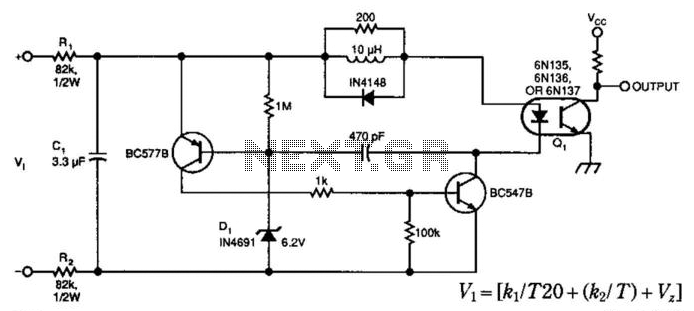
A simple voltage-controlled oscillator (VCO), coupled to instrumentation by an optoisolator, allows for the measurement of high voltages. The component values are suitable for a 0 to 600 V input range, with power dissipation in resistors RI and R2...
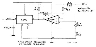
The datasheet contains application circuit diagrams for the L200, including a Programmable Voltage Regulator, a High Current Voltage Regulator with Short Circuit Protection, a Digitally Selected Regulator with Inhibit, a Programmable Voltage and Current Regulator, a High Current Regulator...
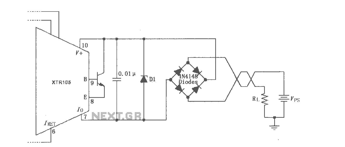
The XTR105 reverse voltage and over-voltage surge protection circuit is illustrated. A Zener diode rated at 36V can be utilized, with options including 1N4753A or 1N6286A. The maximum supply voltage (Vps) should be less than the minimum breakdown voltage...
The circuit depicted can be utilized to operate at a voltage of +5V for Single Board Computer (SBC) power, preventing damage caused by over-voltage from the power supply throughout the SBC. This circuit serves as a protective mechanism for Single...

The power supply varies, and the circuit must operate at under 10 µA of current (excluding the capacitor charging). It triggers a Silicon Controlled Rectifier (SCR) every 10 to 30 seconds as long as the power supply is above...
The DC voltage for the generator field winding is supplied by a three-phase thyristor rectifier. In instances of incorrect operation, phase misalignment, or system failure, the rectifier may generate hazardous conditions, leading to over-voltage insulation issues on the DC...