
4-channel amplifier
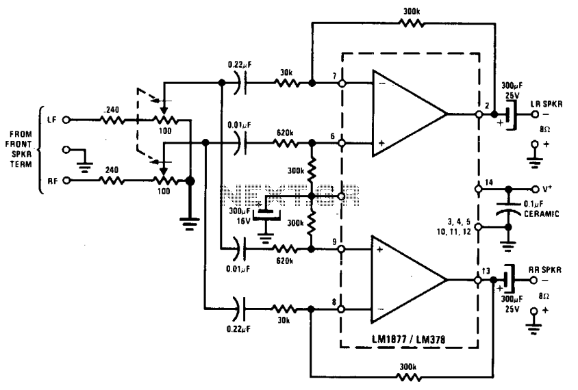
The implementation of a rear channel ambience circuit in a stereo audio system involves the extraction of the difference signal between the left and right channels. This process enhances the spatial characteristics of audio playback, providing listeners with an immersive experience akin to that of a concert hall. The LM1877 integrated circuit is utilized for its efficiency and low power requirements, making it ideal for driving rear speakers without necessitating extensive power amplification.
To set up the circuit, the existing speaker output terminals of the stereo system are utilized as input connections for the ambience circuit. These terminals deliver the left (L) and right (R) audio signals to the LM1877, which processes the signals to create the desired ambience effect. The outputs of the LM1877 are then connected to two additional rear speakers, which are crucial for creating the immersive sound field.
Correct phase alignment is vital for optimal performance. The rear speakers must be connected in the opposite phase to the front speakers. This configuration is denoted by the +/- signs, ensuring that the sound waves from the rear speakers complement the front speakers, enhancing the depth and richness of the audio experience. Failure to connect the rear speakers in the correct phase may result in a hollow or disjointed sound, undermining the intended ambience effect.
Overall, the addition of a rear channel ambience circuit represents a straightforward yet effective method for enriching the auditory experience in a stereo system, allowing users to enjoy a fuller and more realistic sound reproduction.Rear channel "ambience" can be added to an existing stereo system to extract a difference signal (R - L or L - R) which, when combined with some direct signal (R or L), adds fullness, or "concert hall realism" to the reproduction of recorded music. Very little power is required at the rear channels, hence an LM1877 suffices for most "ambience" applications.
The inputs are merely connected to the existing speaker output terminals of a stereo set, and two more speakers are connected to the ambience circuit outputs. The rear speakers should be connected in the opposite phase to those of the front speakers, as indicated by the +/- signs. 🔗 External reference
Related Circuits
The TDA 2030, produced by SGS Ates, is a complete audio amplifier. It is a Class AB amplifier capable of delivering 14 watts into a 4-ohm load with a power supply of ±14V. By connecting two TDA2030 amplifiers through...
Circuit stereo TDA2822 audio power amplifier circuit schematics. In this series, the TDA2822M IC is utilized as the primary amplifier. Additionally, alternatives such as KA2209 and NJM2073 can also be employed. The TDA2822 audio power amplifier circuit is designed to...
The converter depicted in Figure 1 utilizes a component from the PeakSwitch family (U1, a PKS606YN) to operate a 36 W motor, capable of handling startup and load transition peaks of up to 72 W. The motor speed can...
This amplifier circuit is designed to enhance TV signals in the UHF range. It employs a low-noise transistor, providing an amplification of 10 to 15 dB within the frequency spectrum of 400 MHz to 850 MHz. It is crucial...
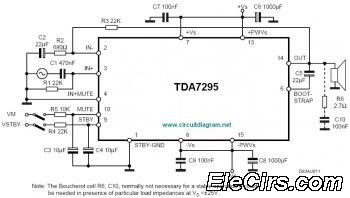
The IC TDA7295 is a monolithic integrated circuit designed for use as an audio class AB amplifier in high-fidelity applications, including home theaters and high-end televisions. The TDA7295 is a versatile audio amplifier that delivers high-quality sound reproduction, making it...
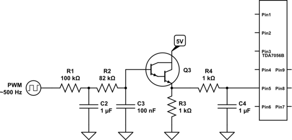
A voltage between 0.4 and 1.2 V is required on pin 5 to control the gain. In the initial two versions of the circuit, logic ICs and/or counters were utilized along with an operational amplifier and a resistor network...