
UHF Antenna Amplifier Circuit

This UHF TV antenna amplifier circuit is an essential component for improving signal reception in the UHF frequency range, which is particularly important for modern television broadcasts. The low-noise transistor is a critical element, as it minimizes the introduction of additional noise into the amplified signal, ensuring a clearer and more reliable output. The specified amplification range of 10 to 15 dB is adequate for compensating signal loss that may occur over long cable runs or due to environmental factors.
The design emphasizes the importance of short wiring connections to reduce parasitic capacitance and inductance, which can degrade the amplifier's performance. Direct soldering of the cable to the PCB not only enhances signal integrity but also minimizes potential points of failure that could arise from connectors.
Installation considerations include placing the amplifier close to the antenna to maximize signal strength before it travels through the coaxial cable to the TV. The waterproof enclosure is vital for protecting the circuit from moisture and environmental damage, which could otherwise compromise functionality.
The use of a choke coil for power supply delivery is a practical solution, allowing the amplifier to draw power without introducing DC voltage into the signal path. The coupling of the coaxial cable to the TV through a small-value capacitor serves a dual purpose: it blocks any DC component from reaching the TV while allowing the AC signal to pass through, ensuring that the television receives only the amplified RF signal.
Overall, this circuit design provides a robust solution for enhancing UHF television signal reception, making it suitable for various applications where signal integrity is paramount.This amplifier circuit is used to amplify TV signals in UHF range. It uses a low-noise transistor and gives 10 to 15 dB amplification in the frequency range from 400 MHz to 850 MHz. The transistor must be shielded from the input components and in constructing this circuit, the wirings must be as short as possible.
For best results, the cable must be directly soldered to the PCB. The circuit should be installed near the antenna and housed in a water proofed case. The power supply for this uhf tv antenna amplifier is fed through the cable by using a choke coil. To prevent the DC voltage from getting into the TV set, the coaxial cable must be coupled to the set through a small value capacitor. 🔗 External reference
Related Circuits
PWM waveforms are widely utilized to regulate the speed of DC motors. The duty cycle of the digital waveform can be established either through an adjustable analog voltage level (as seen in a NE555-based PWM generator) or through digital...
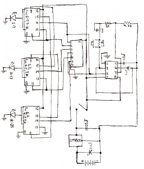
Here is the schematic for the circuit. Solder all the components onto a perfboard. The drawings may not be very clear. Essentially, the 555 timer generates a pulse. The circuit utilizes a 555 timer IC configured in astable mode, which...
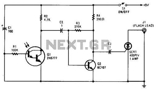
The phototransistor Q1 receives a light pulse from a photoflash unit. The pulse is AC-coupled to amplifier Q2, which subsequently triggers SCR1, activating a flash unit connected to J1. The circuit begins with the phototransistor Q1, which is sensitive to...
The circuit was designed to create a line preamplifier using double triode tubes. It consists of three parts, including the main preamplifier. The line preamplifier circuit utilizing double triode tubes is structured to enhance audio signals by amplifying low-level signals...
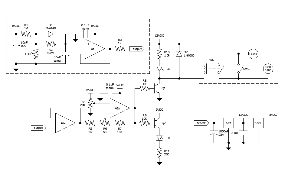
Approximately ten days ago, an all-linear automatic night light circuit was installed to control the lights in the living room. The circuit comprises three operational amplifiers (op-amps): two configured as voltage followers and one as a comparator. As depicted...
The philosophy behind this minimalist design has been explained by Flavio Dellepiane on his highly interesting site. I have myself written an article about this fleapower amp from Italy in the American magazine AudioXpress. All relevant details are published...