
4-channel SQ logic decoder
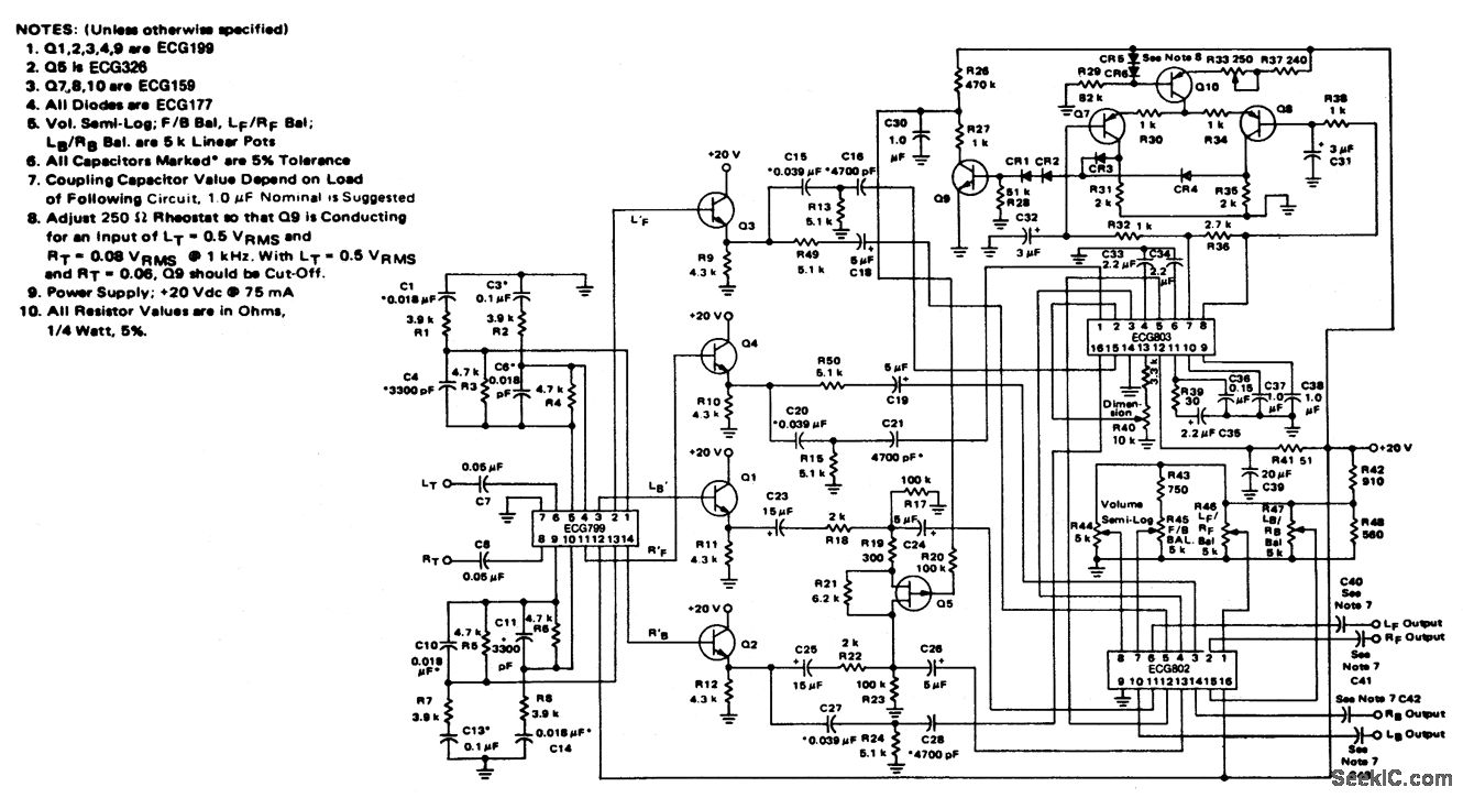
The 4-channel SQ logic decoder is an integrated circuit designed to decode binary inputs into a single active output line corresponding to the binary value of the inputs. This device operates with a current drain of 75 mA when powered at 20 volts, making it suitable for applications where moderate power consumption is acceptable.
The input impedance of 2M ohms ensures that the decoder can interface with a variety of signal sources without significantly loading them down, allowing for better signal integrity. Conversely, the output impedance of 2K ohms facilitates compatibility with standard logic levels and ensures that the decoder can drive subsequent stages effectively without introducing significant voltage drops or signal degradation.
In practical applications, this logic decoder can be utilized in digital circuits where multiple binary inputs need to be converted into a single output line for further processing. It is particularly useful in applications such as data routing, multiplexing, and control systems where the selection of one output from several inputs is required.
The device's design incorporates features to ensure reliable operation across its specified voltage range, and its low power consumption makes it ideal for battery-operated devices. Proper layout and decoupling techniques should be employed in circuit design to minimize noise and ensure stable operation of the logic decoder within the intended application.4-channel SQ logic decoder. Current drain is 75 mA at 20 volts. Input impedance is 2M, while output impedance is 2K (courtesy GTE Sylvania Incorporated). 🔗 External reference
Related Circuits
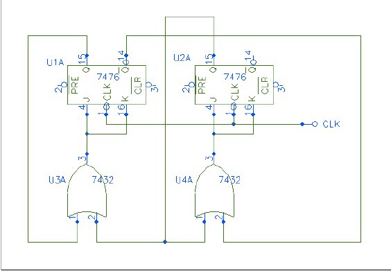
Q1 and Q2 form a table. On the left side, list the four possible states of Q1 and Q2; on the right side, write the values that Q1 and Q2 will assume after the next clock pulse. The table...

All of my turbine starts before the research on the ECU involved a very successful spark ignition. I thought (only briefly) of trying to add spark ignition to the ECU, but the mixture of delicate logic circuitry and perhaps...

This document presents a set of plans for constructing an affordable, high-performance digital logic probe that can be assembled within a few hours. The design utilizes a plastic ballpoint pen as the chassis, providing a unique and stylish appearance....
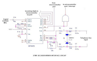
This is a straightforward circuit utilizing the DTMF decoder MT8870 (or CM8870). As illustrated in the circuit, an interrupt will be generated (if the NAND output is connected to the INT of the microcontroller) whenever a call is received...

The circuit presented utilizes NAND logic gates from the Hitachi HD series, specifically the HD74LS00, which is a quad NAND integrated circuit. A special technique has been implemented to achieve three-state operation using a single IC. Gate N1 is...
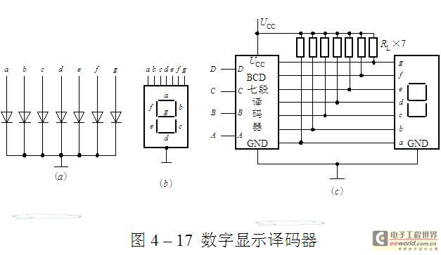
The luminescent diode (LED) is constructed from gallium arsenide (GaAs), a specialized semiconductor material, and gallium arsenide phosphide. It can be used individually or assembled into segment-type or lattice LED display devices. The display unit consists of a sectional...
Warning: include(partials/cookie-banner.php): Failed to open stream: Permission denied in /var/www/html/nextgr/view-circuit.php on line 713
Warning: include(): Failed opening 'partials/cookie-banner.php' for inclusion (include_path='.:/usr/share/php') in /var/www/html/nextgr/view-circuit.php on line 713