
Design Caller ID using DTMF decoder MT8870
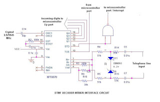
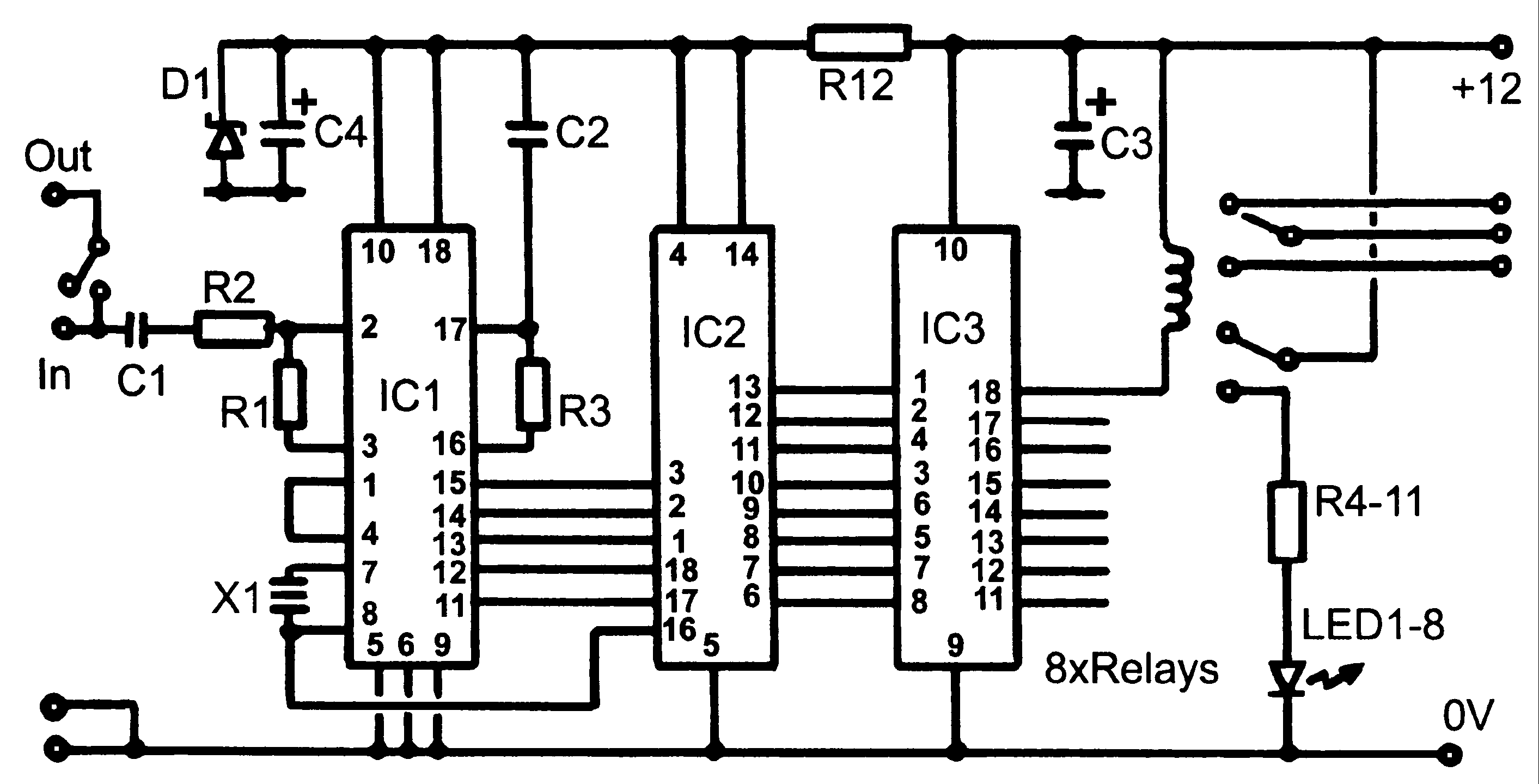
The circuit operates by decoding Dual Tone Multi-Frequency (DTMF) signals, which are used in telephone dialing. The MT8870 is a highly integrated DTMF decoder that converts the audio frequency signals generated by the telephone keypad into a binary-coded decimal (BCD) output. The circuit typically includes a power supply circuit, the MT8870 chip, a NAND gate, and a microcontroller interface.
When a call is initiated or received, the DTMF signals generated by the telephone keypad or line are fed into the MT8870. The chip processes these signals and outputs the corresponding BCD values on its output pins (11 to 14). The NAND gate connected to the output serves as an interrupt signal generator, which alerts the microcontroller to read the output data.
In this design, additional functionality is implemented to categorize the call types. For instance, the microcontroller can be programmed to keep track of received calls, missed calls, and dialed numbers, thus maintaining a log of the user's telephone activity. Furthermore, a telephone directory can be integrated, allowing users to associate specific numbers with names for easier identification.
The circuit layout should ensure proper routing of signals and power supply lines to minimize noise and interference. Proper decoupling capacitors should be included near the power pins of the MT8870 to stabilize the voltage supply. Additionally, the microcontroller should be configured to handle the BCD outputs efficiently and provide user-friendly feedback, such as displaying the number or calling status on an LCD or LED array.
Overall, this circuit design provides a robust solution for decoding DTMF signals while enhancing user interaction through call management features.It`s very simple circuit using DTMF decoder MT8870 (or CM8870). As shown in the circuit, u`ll receive an interrupt ( if NAND output is connected to INT of the microcontroller) whenever u receive a call or make a call and then u can use yr program to read the digits coming out of pin 11 to 14 of the MT8870. I designed the circuit with additional features like seperating received calls, missed calls, dialled numbers along with telephone directory.
🔗 External reference
Related Circuits

This design outlines a fire alarm circuit that utilizes a light-dependent resistor (LDR) and a lamp to detect fire. The alarm is activated by sensing the smoke produced during a fire. When smoke is present, it obstructs light from...
This audio processor circuit features the SSM2045 integrated circuit (IC), designed specifically for electronic music applications, along with the 741 operational amplifier (op-amp) IC. The circuit is configured as a low-pass filter with a DC voltage control for gain....
The motion games on the Nokia 5800 sparked an interest in creating a real-world version of a racing car controlled by tilting a phone. The motion-controlled robot, named Hercules due to its high torque and speed, is operated via...
The circuit operation begins by transmitting stereo surround sound signal quality information through the master volume circuit. This drives the left channel connected to the LCH Model TL072 IC1A and IC1B, which are linked to the right channel (Rch)....
Control monitoring equipment at a TV repeater site is designed to accept commands sent as DTMF tones over the repeater's audio channel. It is capable of switching either AV signals or power supply feeds with currents up to 1...
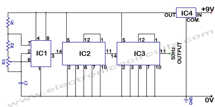
Accurate 50Hz Oscillator Circuit Using 555 and 7490. This circuit generates a 50Hz pulse. It consists of a 555 timer and two 7490 divide-by-ten counters. The circuit utilizes a 555 timer configured in astable mode to produce a square wave...