
4 channels Lamp organ

The described light organ circuit operates by responding to audio signals from an amplifier, allowing lamps to illuminate in sync with the rhythm of the music. The core functionality begins with the audio input being amplified using a transformer (TR1) with a turns ratio of 1:4, which increases the voltage level of the audio signal for further processing.
Following amplification, the signal is filtered through a series of monophonic filters composed of resistors (R1-R4) and capacitors (C1-C7). These filters separate the audio signal into distinct frequency bands, enabling the circuit to control different lamps (L1-L4) based on the frequency content of the music. The triacs (T1-T4), specifically TIC 206 types, are employed to switch the lamps on and off in response to the filtered audio signals. Each triac corresponds to a specific frequency range: T1 is dedicated to bass frequencies, while T4 is tuned for higher frequencies.
Potentiometers (P1-P5) are integrated into the circuit to adjust the sensitivity of the triacs and the overall circuit. P1 manages the general sensitivity, while P2 to P5 fine-tune the sensitivity for each individual triac, allowing for a customizable response to the audio input.
The components are carefully selected to handle the power requirements of the circuit. Resistors are rated at 0.5 W, with values of 100 Ω for R1 and R2, 220 Ω for R3, and 47 Ω for R4. Capacitors are used to filter and stabilize the signals, with values ranging from 680 nF to 10 µF. The transformer is specified to have 100 primary turns and 400 secondary turns, constructed from copper wire with a diameter between 0.1 mm and 0.3 mm, ensuring efficient signal handling.
It is crucial to utilize plastic potentiometers with ash and mica plates in this circuit to maintain thermal management, as the triacs can generate significant heat during operation. The maximum lamp load for each triac is rated at 600 W, ensuring that the circuit can handle substantial lighting demands while operating safely within its designed parameters.This light organ is on the speaker output of the amplifier. The lamps lit on the rhythm of the music. The input signal is amplified by a transformer. Then it goes through a monolingual filters comprising resistors and capacitors to the pots and then to the triacs. By the filters respond to each triac a separate frequency, T1 is the bass and T4 for the high. P2 to P5, the sensitivity for each set triac. P1 controls the sensitivity of the whole circuit. Parts List R1, R2 = 100 ? / 0.5 W R3 = 220 ? / 0.5 W R4 = 47 ? / 0.5 W P1 = 100 ? P2-P5 = 500 ? C1 = 100 V nF/500 C2 = 220 nF The transformer itself should probably be wrapped. This may in 100 primary and 400 secondary windings of copper wire with a diameter of 0.1 to 0.3 mm. Note the fact that the whole circuit power flows. Therefore, only use plastic pots with ash and mica plates as you want cool triacs. C3 = 1 uF C4 = 10 uF C5 = 4.7 uF C6 = 820 nF C7 = 680 nF T1-T4 = TIC 206 L1-L4 = 600 W max lamp TR1 = 1:4 transformer 🔗 External reference
Related Circuits

This circuit is designed to convert continuously lit lamps into flashing lights. It can be easily integrated into an existing circuit by inserting it between the lamp and the negative supply. It is particularly suitable for use with car...
The image 3-6 depicts a thermistor temperature or frequency conversion circuit. The resistance of thermistors changes linearly with temperature, allowing this change to be utilized in a voltage-controlled oscillator. In the circuit, operational amplifiers A1-A4 are current-type LM3900 models,...
In this circuit, a 120VAC lamp is slowly illuminated over an approximate 20-minute period. The bridge rectifier supplies 120 DC to the MOSFET and 60-watt lamp. A 6.2K, 5-watt resistor and zener diode are used to drop the voltage...
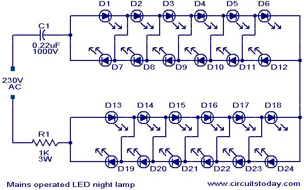
This is a simple and effective LED-based night lamp circuit that can be powered directly from a 230V mains supply. The circuit uses a total of 24 white LEDs and produces an output of approximately 15W. The resistor R1...
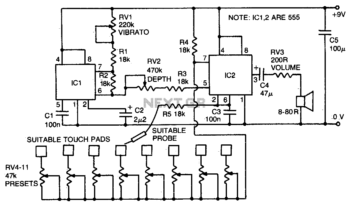
IC2 is an audio frequency oscillator. Its frequency is primarily controlled by the resistance between pins 2 and 7. RV4-11 controls the oscillator frequency, and by touching a stylus (connected via limiting resistor R5 to pin 2) to each...
Capacitors C1 and C2, in conjunction with a speed controller, function by receiving voltage at the gate of the MOSFET. When the voltage on C is applied, it activates the operation of the MOSFET. In this circuit configuration, capacitors C1...