
lamp flasher circuit with mosfet irf511
In this circuit configuration, capacitors C1 and C2 play a crucial role in managing the gate voltage of the MOSFET, which is essential for controlling its switching behavior. The speed controller modulates the voltage supplied to the gate, allowing for precise control over the MOSFET's operation. When the voltage across capacitor C reaches a specific threshold, it triggers the MOSFET to turn on, enabling current to flow through the load connected to the MOSFET.
The design typically involves a feedback mechanism where the speed controller continuously monitors the output speed of the motor or device being controlled. Adjustments to the gate voltage are made based on the feedback received, ensuring that the MOSFET operates efficiently and responds to changes in load conditions.
Capacitors C1 and C2 are selected based on their capacitance values, which affect the time constant of the charging and discharging cycles. This time constant is critical for determining the responsiveness of the MOSFET to changes in the gate voltage, thus influencing the overall performance of the speed control system. Proper selection of these components is vital for achieving the desired dynamic response and stability in the circuit.
The MOSFET itself is chosen based on its voltage and current ratings, ensuring it can handle the load requirements without overheating or failing. Additionally, the gate resistor may be included to limit the inrush current to the gate, protecting the MOSFET from potential damage during operation.
Overall, this configuration exemplifies a common approach in electronic speed control applications, utilizing the properties of capacitors and MOSFETs to achieve efficient and effective motor control.C1 and C2 with a speed controller works by receiving the voltage at the gate of the MOSFET when the voltage on C turn ON the other would be to drive MOSFET operation. 🔗 External reference
Related Circuits
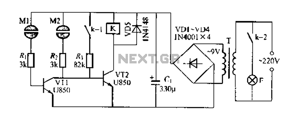
The Darlington circuit is a double-clamp touch switch circuit that features a touch-sensitive sheet and operates with a 20V AC mains supply through an isolated power transformer, ensuring relative safety. Once powered, a 20V optional AC transformer (T) is...
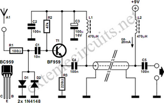
Function: step down the antenna impedance from high to 50 ohms and not, as would be expected, to effect a change from balanced to unbalanced. Component: .. In the context of antenna systems, impedance matching is crucial for maximizing power...
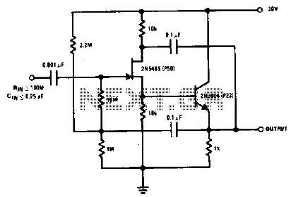
The 2N5485, which has a very low-capacity legacy, is always operated as a source follower with gate bias bootstrap. In this circuit, nothing is left to chance in reducing input capacitance. The 2N5485 is a JFET (Junction Field Effect Transistor)...
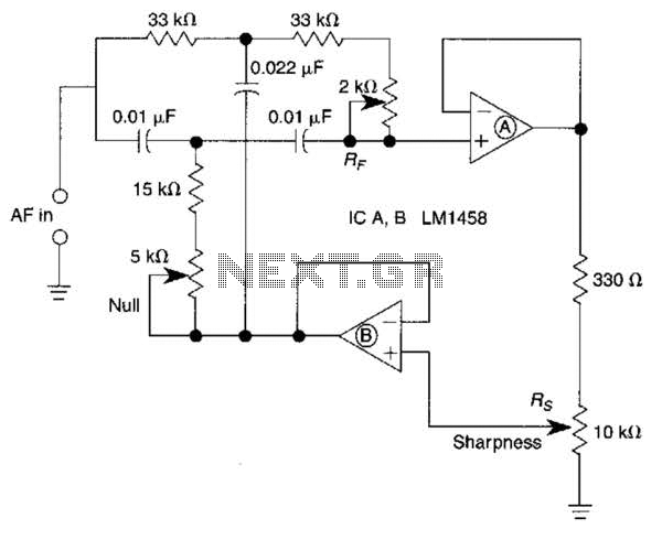
A bootstrapped twin notch filter in this circuit can yield an effective Q of up to 10. Rs adjusts the feedback, hence the Q. Values of C1 and C2 can be changed to alter the frequency. RF is a...
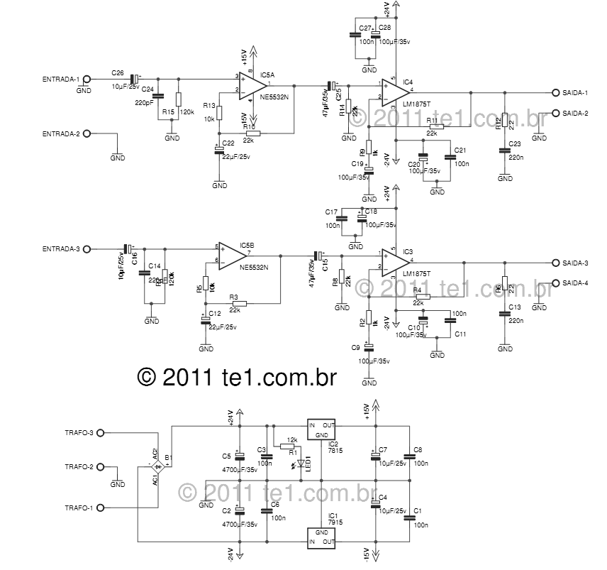
The LM1875 delivers 20 watts into a 4 or 8-ohm load on ±25V supplies. Using an 8-ohm load and ±30V supplies, over 30 watts of power may be delivered. The amplifier is designed to operate with a minimum of...
The circuit indicates two different water temperature trip points by activating LEDs when the specified temperatures are reached. It is built around the LM2904 dual operational amplifier, which is powered by a 12 V automotive system. A thermistor is...